Tuesday, May 21, 2013

Ignition Basics


Inspection:
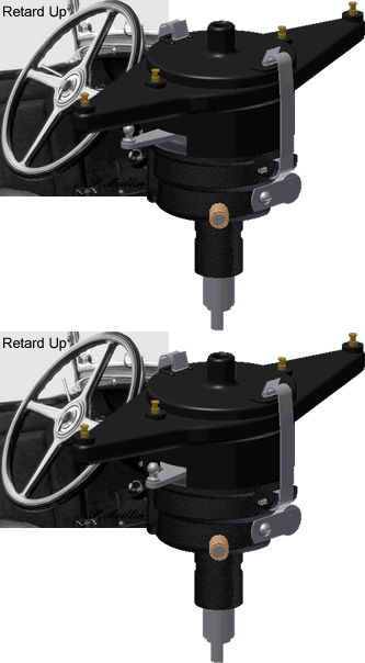
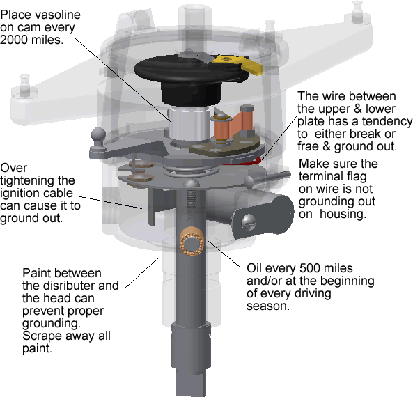
When moving the Spark Advance Lever inside the cab, all the way up and/or all the way down, the spark retard arm on the distributor should not make contact with the Upper Distributor Body on either side.

The fix: For the 29-31 two tooth steering, loosen both steering column clamps. One is inside the cab and the other is under the hood. Rotate the steering column until the arm functions properly. Tighten the clamps.
Inspect the Distributor Shaft.
The Distributor Shaft should not rock back and forth. If it does rock, it is time to replace the bushings.


Slight rotational play is ok.


Setting Rotor/Distributor Contact Gap
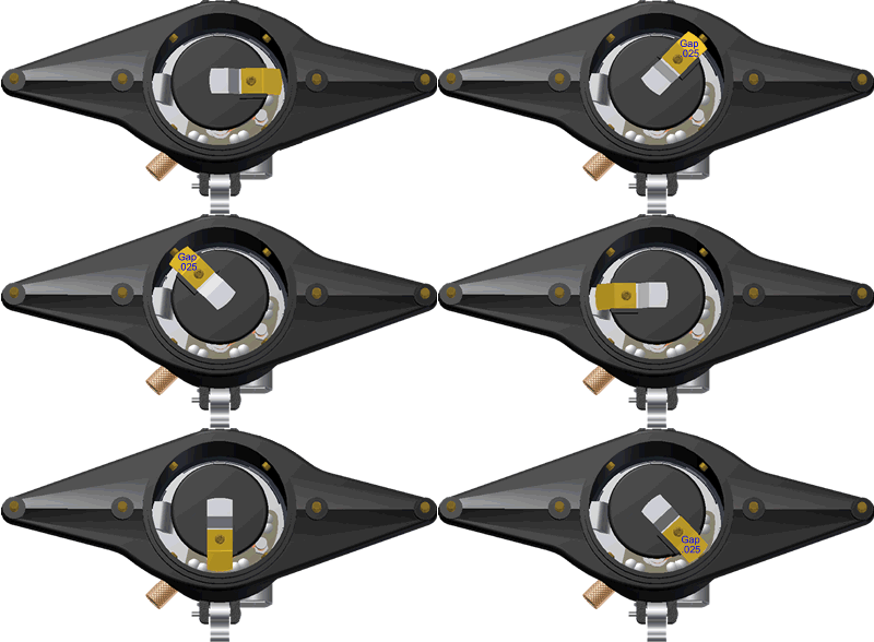
Put on parking brake, place gear shift lever in neutral position, and use the Hand Crank to rotate the rotor.
Check the rotor at all four distributor contact points. The gap should be .025
 
The fix: Bend the Rotor and/or file the contacts on the Distributor Housing.

Setting Point Gap
To adjust points proceed as follows:
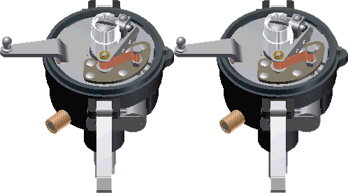
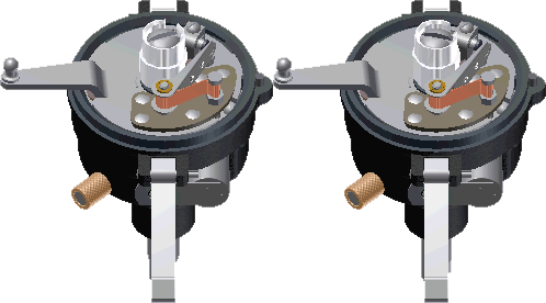
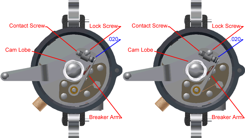
1. Lift off distributor cap, rotor, and body. Turn engine over slowly with hand crank until breaker arm rests on one of the lobes of the cam with the breaker points fully opened.
2. Loosen lock screw and turn the contact screw until the gap is between .018 and .022”. A standard thickness gage is used to obtain this measurement. When correct adjustment is obtained, tighten the lock screw. After tightening the lock screw, again check the gap to make sure the adjustment was not altered when the lock screw was tightened.
3. Replace distributor body, rotor and cap or proceed to ignition timing.
Ignition Timing:
1. Inspect the Distributor as stated above.
2. Put on parking brake
3. Place gear shift lever in neutral position
4. Fully retard spark lever.
5. If not previously done, remove the distributor cover and lift off rotor and distributor body.
6. Check Point Gap. If necessary adjust them as previously described above.

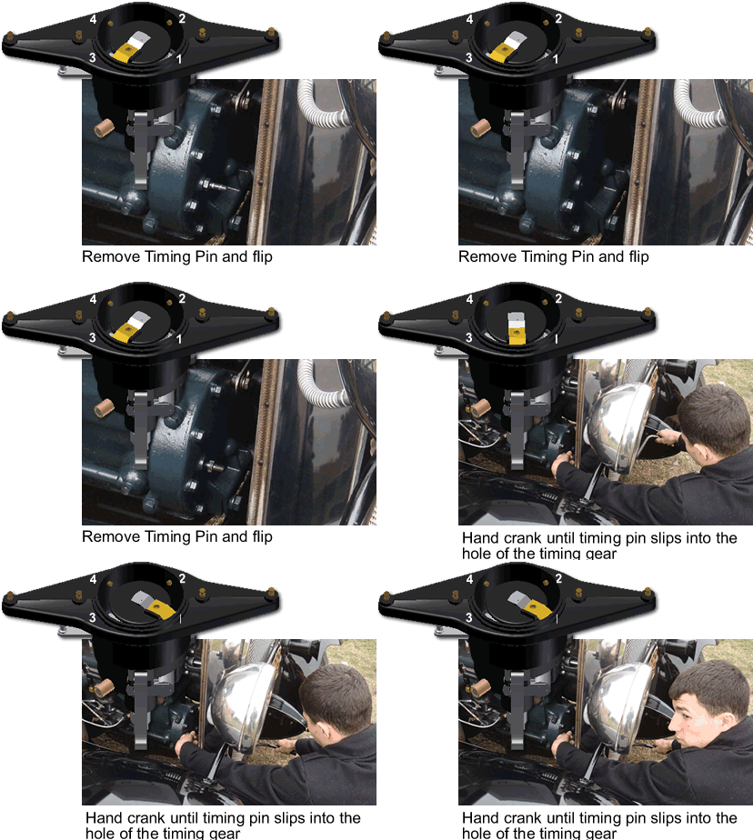
7. Screw out timing pin located in timing gear cover and insert opposite end of pin into opening.
8. Find Top Dead Center. With the hand crank, turn the engine over slowly, at the same time pressing in firmly on the timing pin. When piston # 1 reaches the end of the stroke (top), the timing pin will slip into a small recess in the cam gear.
Tip: If the engine had been running recently, the timing pin should drop into the recess when the rotor is about to line up with contact #1 on the distributor cap.
Note: While hand cranking to find the timing mark mark, occasionally pause to relieve the compression pressure.
Note: If the timing mark is missed it is two revolutions, with the hand crank to return to the previous point.
Note: By removing Plug # 1 and shining a small flash light into the hole, it is possible to see the top of the piston when you are at Top Dead Center.
Note: By removing all the plugs, the compression is eliminated and the engine is easier to hand crank.
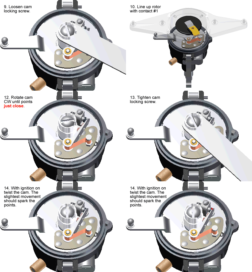
9.Remove the cap and rotor. Loosen cam locking screw until the cam can be turned. Note: A cam wrench can be purchased from one of the Model A venders, makes the job easier.
10. Replace rotor and/or use the cam wrench to turn and line up the notch in the cam with the No1 contact point on distributor head.
11. Remove rotor and/or wrench from cam and using your fingers slightly turn the cam in a counter clockwise direction, until the breaker points are fully opened.
12.Slowly turn the cam back in a clockwise direction until the points just close.

13. Lock the cam by securely tightening the cam locking screw. This method removes the backlash in the distributor shaft from affecting the timing.
14.Turn on the ignition and with your fingers twist the cam counter clockwise. With the slightest movement the points should spark. If it does not spark retime.
Final check with the ignition on pull the spark advance lever down one or two notches and listen and/or have someone watch for a spark from the points. If the lever moves more then three notches retime.
Replace timing pin and put away crank
Oil the distributor and Apply Vaseline to the cam.
15. Reassemble distributor housing, rotor, and cap

Model A's are positive ground. The Model A frame acts as the positive ground wire from the battery
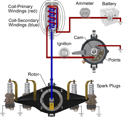
The Primary Circuit.
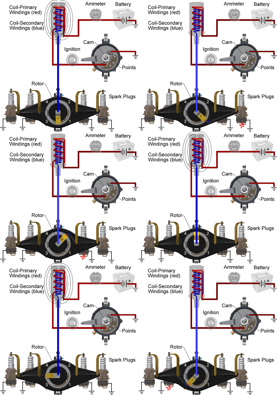
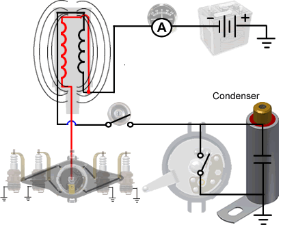
The primary circuit is the low voltage circuit that controls the ignition system.
  • Battery - provides the power to run the system.
  • Ammeter - Used to measure the current flow.
  • Ignition Switch - allows the driver to turn the system on and off.
  • Points - a mechanical switch that acts as the triggering mechanism to break the circuit to collapse the magnetic field in the coil.
  • Condenser - provides a false ground and protects the points from burning out.
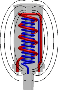
  • Primary Coil - produces the magnetic field which collapses and creates the high voltage in the secondary coil.
  • Wires - join all the components together.
  • Model A Frame - acts as the positive wire used for ground.
The Secondary Circuit
The Secondary Circuit is the high voltage side of the ignition system. The voltage is generated when the magnetic field collapses in the primary windings.
  • Secondary Coil -Creates a high voltage when enacted upon by the collapsing of a magnetic field in the primary coil.
  • .Coil Wire - a highly insulated wire, that takes the high voltage from the coil, to the distributor cap.
  • Distributor Cap - a plastic cap with an electrode to distribute the electricity to the rotor.
  • Rotor - spins around on the top of the distributor shaft, and distributes the spark to the right spark plug.
  • Plug Connectors- metal strip that takes the high voltage from the cap to the plugs.
  • Spark Plugs - Highly insulated electrode that forces electricity to arc across a gap in order to ignite a fuel air mixture in a combustion chamber of an engine.
Primary and Secondary System
The ignition switch allows the driver to turn the system on and off. Turning the key to the on position closes the circuit and allows current to flow. As current flows around the primary coil, a magnetic field is created. The strength of the magnetic field is determined by how long the points are closed.
The points act as a mechanical switch that is controlled by the distributor's cam. When the points open, the circuit is broken; this instantly collapses the magnetic field and induces a high voltage into the secondary windings. The voltage is so intense that in its path to ground, it is able to ionize the air gap of the spark plug, thus igniting the fuel air mixture in the combustion chamber.
How The Condenser Works
The function of a condenser is to provide a false ground. When the points open and the magnetic field collapses in the coil. A high voltage is created in both the primary and secondary windings. The voltage in the secondary windings heads towards the spark plugs to ignite the fuel; while the new induced voltage in the Primary windings searches for ground. The voltage created by the collapsing of the magnetic field in the primary coil is strong enough to jump the gap between the points in the distributor as they open, but instead, the current is attracted to the condenser, where it is collected and stored to assist in the next cycle of creating a magnetic field in the Primary Coil.
Note: At one time the condenser was considered the weak link in the system and failed often. Today's reproduction condensers do not fail like their predecessors and are quite reliable.

Tom Wesenberg Tip:
"Condensers are very easy and quick to change if you follow these steps exactly.
1. Have the new condenser lying next to the distributor.
2. From the passenger side, remove the ground screw FIRST.
3. From the driver’s side remove the condenser terminal screw and be sure to keep light pressure on the screw while you slip out the old condenser and slip in the new one.
4. Tighten the terminal screw, then go to the passenger side and tighten the ground screw.
Always set the points to .020” first, then set the timing. Remember that the points setting can affect the timing, but the timing can’t affect the points setting. Be sure to have lube on the points rubbing block. I always carry a small piece of sandpaper in my billfold just in case I need to clean points, or check an engine number at a swap meet, etc. A points file is good to keep in your car’s tool kit and only costs about a dollar."

How The Coil Works
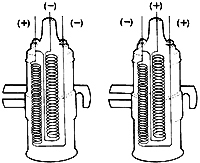
The coil itself does not care which way it is hooked up, it will be just as efficient either way. On the other hand the spark plugs do care. They prefer the center electrode to be negative and the end electrode to be positive. The reason is electrons like to jump from a cold surface to a hot surface and the center electrode of a spark plug is hotter than the end electrode. By correctly establishing the coil’s polarity the voltage required to jump the spark plug gap is 15 to 30 percent stronger which may or may not be evident on the performance of your ‘A’ depending on the condition of the ignition components. Oddly enough the large amount of voltage created by the coil is not affected, positively or negatively, by the mere 6 volts (or 12) of the battery. Therefore; positive ground or negative ground of the battery is not relevant.
Tom Wesenberg Tip:
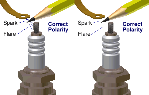
"To check coil polarity hold a pencil lead in the spark path with the plug wire about a third of an inch away from the distributor terminal. You’ll see a FLARE on one side of the pencil lead and this flare should be on the spark plug side of the lead." Tom suggests to hold the pencil in the middle or even slide the pencil into a plastic tube to avoid an electrical shock.
If the flare is on the plug wire side. Switch the two wires on the coil.
Restoration Tips by Tom Endy
Distributor Techniques
Numerous articles have been written concerning the rebuilding of the Model A Ford distributor. Just about any one of them will get you through the rebuilding process. The intent of this article is to provide some tips to help you do the job better.
Distributor Roadside Seminar
On any long club tour sooner or later one of the Model A's will pull over to the side of the road and up will come the hood. The first component to be attacked is the distributor, and it is probably the most likely source of the problem..
Model A Ford Ignition Diagnostic
Ammeter "Jiggle"... A wealth of knowledge:
The Ammeter
The ammeter in a Model A Ford can be a very useful tool in a variety of situations that will signal to the driver the car’s electrical status.


 Source:  http://modelabasics.com/Ignition.htm

Coil Polarity

I was converting my older Euro car over from positive to negative ground when I came across the question of coil polarity. I discovered coil polarity is very much misunderstood. In researching it, I was very confused until I found out there are two definitions of coil polarity. I talked to three or four knowledgeable people on the subject and read several technical books and articles. Everything made sense in itself but didn't jive together until I found out they were talking apples and oranges.

Definition #l Coil Polarity (In relation to battery)

The polarity of the coil should match that of the battery by connecting it so (+) goes to (+) and (-) connects to (-). But don't worry about which way you install the battery (positive or negative ground) or which way you install the coil (regardless of coil markings) it will automatically adjust itself. The coil will work efficiently and put out the same voltage either way it is hooked up, but the spark plugs are more sensitive when it comes to polarity, hence our second and more important definition.
Definition #2 Coil Polarity (In relation to spark plugs)

Coil polarity should be such so as to provide negative polarity to the spark plugs center electrode.

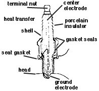
It has been found that it takes approximately 15% less voltage to form an arc at the plugs, if the hotter center electrode is negative, and the cooler (by comparison) ground electrode is positive. The center electrode is hotter since heat transfer from the tip must make its way through the porcelain insulator past the sealing gaskets to the shell block and then to the water jackets.

If your center electrode is positive, your car will probably still run fine until, with its 15% handicap, it exceeds the coil output. If you live where temperatures dip down to 0° you may not get your car started. Driving with a full load and accelerating hard up a hill may cause an ignition miss. If your ignition system is well worn to where you have various voltage losses, you could get a miss.

Correct coil polarity won't eliminate these problems, just put them off by 15%.

If your coil has - & + markings by the primary terminals, you will be pretty safe by hooking it up by those marks, but test it for correct polarity anyway, using one of the tests listed further on. If your coil has CB & SW or BAT & DIST markings, there is no way of telling if the coil was marked in relation to a positive or negative ground car, and the only sure way to tell if the coil is installed right is to test it out.


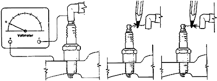
You test for correct polarity by hooking up a voltmeter with the negative lead to the plug terminal (which should be of negative polarity) and the positive lead to the block (which should be of positive polarity). Set the meter on the highest volt range. These connections remain the same whether you have a positive ground or negative ground electrical system. The secondary winding's polarity which we are testing is determined by the combined hookup of the battery and primary windings, so it may or may not match the battery's ground.

Cranking the engine over (you don't have to start it) should show an upward swing of the voltmeter needle (don't be concerned with taking a reading). If the needle swings down off the scale, your coil is hooked up wrong. To correct, reverse coil primary leads. Do not worry about the coil markings (refer to definition #1).

If you don't have a voltmeter, test by removing a plug wire from a plug and hold a plain lead pencil point in the path of the arc. A flair (hard to see) towards the plug shows correct polarity while a flair towards the coil shows reversed polarity. 


_________________________________________________________________________

Ford Barn Thread:

Original Post:  

In the Model A Ford Mechanics Handbook by Les Andrews, shows the  Black wire from the coil connecting with the Yellow/Black Tracer wires on the driver's side terminal of the box. This would then be routed by the Yellow/Black Tracer to the Ampmeter charge side and to the generator cut out. The instructions here seem to  be helpful because they identify "drivers" or "passengers" side.

*In the original Ford service bulletins, the Black wire goes to the terminal with the Yellow wire connections ( Fig 444). This would be routed to the Ampmeter discharge post and the Starter Motor
terminal. No mention of drivers or passengers side.

Also, my coil is a slant pole and does not indicate which side is positive and which is negative (drivers or passengers side would be really helpful here). Les Andrews says the red wire from the ignition switch should to the positive coil post. Therefore, the black wire should go from the negative coil post to the Ampmeter / Generator terminal post which would be Yellow / Black Tracer??

Can anyone shed some light on this wiring contradiction? I have thoroughly confused myself. But the two diagrams are clearly different.

Response #1:

Either wiring will work. The only difference is that one will make the ammeter needle twitch a little bit when you turn the key on and crank the engine (because the power going to the coil from the battery has to go through the ammeter). The other will not make the needle move because the current is taken from the battery before the ammeter.

I like having the ammeter needle move a little bit when I turn the key on and crank. It confirms that the points are working. To do that, take the power feed for the coil on the generator side of the ammeter, not the battery side.


Response #2: 
If you look closely at the Service Bulletin on the wiring change you will see that with the slant poll coil you need to crisscross the black wire from one side of the coil to the opposite side of the terminal box. This changes it for the ignition to read through the ammeter while retaining proper polarity of the slant pole coil.

Response #3:
If you read the service bulletins you will see that a change was made to the ignition circuit to pick up it's power after the amp meter. I have no idea why the original design had the ignition circuit not flow through the amp meter.


Response #4:
About the same time Ford switched sides for the feed wire, they switched coils from slant pole to straight pole. To add to the confusion Ford switched polarity on the coil posts when they switched the wiring to run the coil through the ammeter. However, a few slant pole coils were made with the polarity the same as the new straight pole coils. So, on ALMOST all slant pole coils, the driver's side is the red wire, which leads to the switch, then points, and is the POSITIVE side.

See page 390 in the Service Bulletins. If you have any questions about coil polarity, check out what is posted by the Chicagoland MG club:  http://www.chicagolandmgclub.com/tec...neral/574.html

I did the same as Jim and moved my slant pole feed wire to the other terminal, so the drain would show on the ammeter. Now while the generator is charging, the ammeter shows ONLY the amps going into the battery, where the original way it showed the amps going into the battery, plus the amp or so to run the slant pole coil.

Response #5:
Also, after the latest specified Model A Ford wiring changes, it was recommended to connect all additional Model A electrical items to the Driver's Side Terminal of the fire wall terminal box; however, "if" one obtains & installs "Logo Lite" turn signals, the Logo Lite manufacturer recommends connecting their Logo Lites to the Passenger Side Terminal of the fire wall terminal box.


Source:  http://www.chicagolandmgclub.com/techtips/general/574.html
Source: http://www.fordbarn.com/forum/showthread.php?t=89736

Ignition Trouble Shooting


The Following are MAFCA Starting Points to help you diagnose Model A ignition circuit problems...

Check the Following:
Here are the checks to make:

  • Yellow wire connected from post on starter switch to terminal box post (post on passenger side of terminal box).
  • Ammeter (-) side connects to passenger side post on terminal box.
  • Ammeter (+) side connects to driver side post on terminal box.
  • Black wire connects from driver side post on terminal box to coil (-) terminal.
  • Red wire connects from coil (+) terminal to ignition switch.
  • Yellow/Black wire also connects from driver side terminal box post to the cut out terminal. That completes the ignition wiring except for the ignition cable and distributor plate.
  • Here is a voltage check of the circuit:
  • Connect the (+) side of your volt meter to a good ground point on the engine or frame.
  • Touch the (-) probe to the passenger side terminal box wing nut. Read 6 volts.
  • Touch the probe to the driver side terminal box wing nut. Read 6 volts.
  • Touch the probe to the (-) terminal on coil. Read 6 volts.
  • Touch the probe to the (+) terminal on coil. Read 6 volts.
  • Place a piece of paper between the point contacts.
  • NOW TURN IGNITION KEY ON.
  • Touch the probe to the end of the points arm, read 6 volts.
  • Remove paper between points. Open and close points and look for spark each time points open, (no spark means bad condenser, replace condenser).
  • If points are sparking then disconnect the coil center (high tension wire) from the distributor cap (leave connected at distributor end). Place the free end of the coil wire about 1/8" from one of the engine head nuts. Crank the engine over with the ignition key on. There should be a bright blue arc from the coil wire to the nut (ground point). No arc means bad coil.

Front Alignment


Model 'A' Ford Front Wheel Alignment

The following images and information are taken from the Ford Service Bulletins. Bulletins were sent to the Ford dealers on a monthly basis. Each contained eight to sixteen pages of service procedures, component changes, etc. The original bulletins were 8-1/2"x 11" pages. The front page each month usually contained an image suggesting window displays or other promotion ideas.
The Ford Service Bulletins are available in an undersized book form. Unfortunately the monthly cover pages were omitted to conserve space, but all the other pages are reprinted in their entirety. A full sized version of the Ford Service Bulletins for the Model A years is once again being reproduced and I highly recommend it over the undersized version.

The bulletin states "Pull car forward at least three feet before placing gage in position. Place gage between front wheels with ends of gage bearing against the tires and both pendant chains (6" long) barely touching the floor."
"Test for play in bushings by pressing outward on the front of both front wheels at the same time."
"Set the scale on the gage so that the pointer registers at zero; then with the gage still in place, move car forward until gage is brought to a position back of the axle with both pendant chains barely touching the floor. The pointer will now register the exact amount of toe-in." April 1928 


Additional Notes:


  • With the chains touching the floor, the gage is 6" above the floor.
  • No Model A wheels run perfectly true and as such have some degree of wobble. With the original gage positioned and remaining in place throughout the process as specified, any wobble in the wheels is compensated for completely.
  • If it is desired to service the tie rod (spindle connecting rod) ends without moving the brake housing plates, in most cases it's possible to access the end plugs by turning the steering all the way to one side and access the plug on the opposite side. As a last resort loosen the clamp bolts and unscrew the rod. Both ends should release at approximately the same time. The rod ends may then be turned for access to the end plug. In either case the toe-in will require readjustment. When reinstalling, be sure the clamp bolts face the rear of the car, and that both ends engage the rod at nearly the same time.


How To Apply This Information Today


The wheel image to the left indicates some of the possible measuring points for setting the toe-in. Points "A", are the points used following the original method and measurement (from 6" above the floor). The original specification of 1/16" calculates to .194 degrees toe-in. Using measuring points further from the center (spindle), slightly increases the required toe-in measurement to maintain the same degree of toe-in. Using measuring points "B" or "C" increases the toe-in measurement by 1/50". Using measuring points "D" increases the measurement by 1/27". While the difference seems minimal, it's important to keep in mind when making the final check.
Points "C" and "D" are for measuring at the tread surface (see "Suggestions" below)

Suggestions
The original method is the simplest and most accurate (short of more modern alignment equipment) but not everyone has an appropriate gage. Alternatives include multiple checks to average the different readings obtained from different positions of the tires, or raising the tires off the floor and applying a thin chalk line on the tread surface while slowly turning the wheel and using these lines for measuring points. The latter also compensates for wobble as it applies to measuring and setting the toe-in.
Measuring points "B" and "D" (above) are potentially the best points to use but require a device with angled or offset ends that must NOT flex or distort during the process. Measuring points "A" and "C" are the simplest due to the easy access.
Be sure to drive the car forward a few feet before the first and final checks. The toe-in may be slightly increased (maybe an additional 1/16") to add stability to a loose front end until proper repairs can be made. However, this will increase the wear on the front tires.


Source: http://www.abarnyard.com/workshop/align.htm

Saturday, May 11, 2013

Prehistoric Bangers By Thom Taylor, Photography by Randy Lorentzen


Bangers are bitchin’, and prehistoric bangers are better yet. There are many dedicated fans of the old-and-slow 201ci, L-head four-bangers originally found in millions of Ford Model Ts, and Model A/B/C-equipped ’28–’34 Fords—and especially of the speed equipment manufactured for them. The good news is they’re popular enough that you don’t need to sweat scouring endless swap-meet spaces to score a find—much of it is reproduced and better than new. Bangers are now hotter than ever. 

There was a time when the whole of hot rodding was based on making old Model Ts and later Model As run as fast or faster than anything in Anytown, USA. For the few who could afford it, a reground cam, improved ignition, and an overhead conversion could make a stripped-down roadster dance to the tune of 115 mph on the dry lakes. Bangers were the hardware to beat, even into the Ford flathead V8 era until about 1938, when hot rodders were able to apply their talents to four more cylinders—and the rest is hot rod history. Their depression-era cost and obsolescence after WWII make them a genuine score today.

For those eager to learn more, there’s the Secrets of Speed Society (SecretsOfSpeed.com), which publishes a quarterly journal with lots of tech and also holds meets throughout the year, where you can see and hear first-hand what the commotion is all about for a modest yearly membership.

If you’re ever near Lincoln, Nebraska, Speedy Bill’s Museum of American Speed (MuseumOfAmericanSpeed.com) is a treasure trove of virtually every speed part ever made, including super-rare and one-off banger hardware, plus long forgotten overhead conversions like Cook, Fargo, and Rutherford. 

Once your roadster is running and you’re ready for something more than “motorvating,” the Southern California Timing Association (SCTA) has classes for racing both vintage flathead fours (VF4) and vintage overhead four-bangers (V4)—with Bonneville records of 152.1 mph in Gas Roadster and 169.3 mph in the Fuel Roadster class! Yes, you really can caffeinate half-an-eight. 

Our friends at H&H Flatheads (Flatheads-Forever.com) in La Crescenta, California, have been collecting and assembling hot bangers for years and were kind enough to let us photograph these coveted gems. Check out what vintage speed looks like.

The A-B-Cs of As, Bs, and Cs

All Ford four-bangers are L-head configuration in stock form—which means the valves are in the block. That’s why the overhead conversions are conversions. Riley heads contain the intake valves while retaining the stock exhaust valve location in the block (surrounded by water jackets). Miller heads contain both intake and exhaust valves for a true overhead valve or F-head configuration.

Model A engines are rated at 40 hp stock. They use a smaller crank than their B and C counterparts, and use a gravity-feed or “splash-n-drip” oil system—not a pressurized oil system. 

Model B engines feature a larger crank with no counterweights and a four-bolt water pump. They feature a pressurized oil system with direct lubrication to the mains. The oil galleys can be tapped to provide better lubrication for the crank, cam, and timing gears. 

Model C engines pick up all of the advances of the B, but feature a counterweighted crank, a lighter flywheel—offsetting the crank counterweight’s heft—and a three-hole water pump that will help you eyeball the difference at a swap meet or estate sale. 

Whichever engine is used, H&H modifies the stock oil pump to redirect the oil by running tubes directly to the main and cam bearings and timing gears.

Miller-Schofield Conversions

Hrdp 1210 Vintage Ford Model A B C Four Cylinder Engines 04
The Miller-Schofield overhead conversion was designed by Leo Goosen for race-car builder extraordinaire Harry Miller and was funded by a consortium of businessmen led by George L. Schofield. Their plan was to capitalize on the presumed long run of Model As spewing out of Ford’s plants. Model As were produced from 1928 to 1931. With Miller’s collapsing fortunes, the Miller Hi Speed head tooling was soon sold to Cragar and slightly reworked as a Cragar head sold through Bell Auto Parts. (Yes, Cragar S/S wheels are the offspring of this long-ago race-parts manufacturer.) Among many racing triumphs, the team of Miller and Goosen were best known for developing the Offy engine that dominated Indy for decades. 

Dan Webb’s green B-block seen above started life in his original Model B standard Deuce sedan, stored in a barn for over 55 years! The Burton, Michigan, resident decided to retain it and contacted H&H to do a rebuild with a repro Miller-Schofield overhead conversion. 

Hrdp 1210 Vintage Ford Model A B C Four Cylinder Engines 05
The similar but blingy blue banger below started as a Model A block and is destined for Jim Norman’s ’31 Model A cabriolet from Southern California. Though his A is a restoration, it’s more of a touring car than a show car. 

Both Miller-Schofield conversions run reproduction Stromberg 97 carburetion—a single on the Norman A and a log intake with dual 97s on the Webb B. Additionally, on the Webb engine, a vintage Wico magneto handles spark. 

Internally, H&H assembled both Millers with its private-label cam and forged rods, forged Arias pop-up pistons, steel-sleeved standard-bore holes, line-bored inserts (eliminating the original babbit bearings), Scat crank, and ceramic sealed-water jackets. 

Says Dan, “The sedan loves 60 mph—that’s its sweet spot. There’s still more grunt there, but even at 60, you know this is the fastest this old sedan has ever run.” And the sound? “I ran a 2-inch straight pipe, no muffler, and reduced it to the original, rusted 11⁄2-inch exhaust. It sounds like a screaming banshee and feels like a laser cutter when you walk past it.”

Do “Model C” Engines Really Exist?

Don’t let the old timers tell you otherwise—Ford made lots of Model C engines, though they were not referred to as Model C by Ford. Bangers became an option, not a separate model designation, but the public still called them Model Cs. They were available in both passenger cars and trucks in 1933 and 1934, and they have improvements and differences from their Model B counterparts. Henry Ford used up everything he had in his manufacturing plants, which is why some ’34 Fords ended up with bangers. There were 263,765 Model B and C engines produced between March 9, 1932 and late 1934.
  • Hrdp 1210 Vintage Ford Model A B C Four Cylinder Engines 07
  • Hrdp 1210 Vintage Ford Model A B C Four Cylinder Engines 08
  • Hrdp 1210 Vintage Ford Model A B C Four Cylinder Engines 09

Riley Four-Port Conversions

Hrdp 1210 Vintage Ford Model A B C Four Cylinder Engines 10
The Riley two- and four-port overhead conversions were the brainchild of George Riley, an inventor who also raced cars, planes, and boats. Among other creations, he came up with the inboard/outboard boat engine configuration. 

He opened his shop in 1919 to produce speed equipment for Model Ts and continued to build new Ford speed equipment for years. He also created many wild, one-off race engines, including some cool opposed-two-cylinder midget motors. His four-port head first came on the race scene in August 1932. 

Riley stated that the high point of his career was when the Blue Crown Specials won numerous Indianapolis 500 races in the late ’40s while running his Riley race carburetors. 

The Riley four-port conversions shown on these pages both feature vintage heads—one that’s cast iron from 1938 (red engine), the other a later, rarer aluminum version from 1948 (white engine). Both Rileys are race engines. The white version features original Riley sidedraft carbs sold as a package. In fact, this particular head is as it originally came from George Riley himself. It was built in the ’50s.
Hrdp 1210 Vintage Ford Model A B C Four Cylinder Engines 11

Max Herman Jr. of H&H says the sidedrafts make a direct blast to the cylinders, with no twists or turns like a top- or bottom-draft carburetor—meaning they take in more air quickly. More air in = more power out. 

Besides the Riley carbs, the white engine also features a Model C crank drilled for a pressurized oil system and Buick rods and pistons. Both run bigger, better forged stainless valves, springs, iron guides, and original rockers that are re-bushed and re-shafted. 

The red Riley features the more popular Winfield carburetors run on many a race motor of the era. These, as well as the stalwart Stromberg 97, are what you’ll find on most hopped-up bangers.
Both Riley’s run “split-grind” cams, which means the exhaust lobes are ground differently than the intake lobes—saving wear and tear on the valves as opposed to a race-grind cam used with a high-compression flathead. 

Riley also manufactured a milder two-port head conversion, which can easily be distinguished by the exhaust and intake being located on the same side of the engine.


Source: http://www.hotrod.com/thehistoryof/retrospective/hrdp_1210_vintage_ford_model_a_b_c_four_cylinder_engines/

Friday, May 10, 2013

Model A Ford Tool Kit Early 1928

Model A Ford Tool Kit  ORIGINAL Early 1928 for passenger car & pick-up. This complete Show Quality tool kit includes all ORIGINAL FORD Factory tools ,  including A jack # 17080- by  Walker flip-top a carry-over from Model T, in excellent working condition, it is painted with black enamel and is in MINT Condition . The  jack handle  16" long is a spoon shaped tire iron with 7/16" hole punched in the other this also Mint condition.


 The adjustable wrench shows the small Ford script  embossing at the very top ,the early open end wrenches  have only the Ford Script on one side and a makers mark on the other ,all, are in perfect condition.   The pliers shows the large ford script with 1 1/4" jaw also in perfect cond. The Tire pump with the Ford Script on the right side and hose inlet on the other is stamped on the bottom with T-1434 it has the cast iron base and cast iron screw top, in working condition has ,  an excellent reproduction hose  with Original clamps and nozzle. The hose is assembled at the base with the Original brass hose inlet and a red hard paper gasket.   The Alemite grease gun in good condition with a deep alemite stamping, also included is copy of the Alemite booklet. The screwdriver is in excellent condition. The tire iron 10" long, the first used with the model a (a carry over from model T) , and spark plug wrench ( type III with 3/4" thick box end does  have a script)  are also in excellent condition.   The Ford Instruction Manual Early 1928 # 3  Book ,  showing the early style squeeze grip center emergency brake handle and mushroom style gear shift knob.The book is in  good Condition , showing some soiling on the  cover and some water staining at the back of the book.  .  The Tool Bag is in  rough condition, this is the earliest type and Very Rare, the material appears to be a black pebble grain artificial leather,It has a  one snap common sense twist type in the center  . The hand crank is the very first one supplied with the 1928 model  A. The socket end has the 1" outside diameter while the lug end has the pinched or under cut end. Also each bend is 90 degrees as the later versions have 106 degrees. This Tool Kit is Ready for Display with your Blue Ribbon Show Car.

Diamond Block Model B Ford Engine

What I know about the Diamond block:

The Diamond was the factory identification for post production replacement manufactured engine parts. The blocks had a diamond cast into them just above the cam gear inspection cover. The heads had the diamond cast under the water pump boss. There were A diamond blocks and B diamond blocks. The Diamond block castings are the same as what ever the factory was making when they stoped putting them in production vehicles.

Diamond A engine-

Same as the late '31 block. only difference I've seen is the rear main boss is beefier. Some people have noted hardened valve seat in the exhaust. No verification that this was done by the factory. There are reports of people that have these engines with counter weighted cranks, but if they did come from the factory that way, then they were very late (40's prewar) replacement engines with the pinned on counter weights.


Diamond B engine -

Block is same as last of the production build. Not all had counter weighted cranks. These were avalible as complete engines OR bare blocks. If you needed a new block this is what you got from the dealer as a replacement. Diamond blocks do not always mean that there is a counterweighted crank inside!!!!!!!!! I've been told that the casting is thicker in some areas, but I have not fond anything to document that.

The easiest way to tell if the engine has counter weights is to pull the breather tube and shine a flash light down in through the hole in the block. if you rotate the crank, you can see the #2 crank throw. If you see weights, your Money.