Sunday, December 21, 2014

1934 Radiator Shells


Down and dirty version of how to identify a '34 radiator shell from an eBay correspondence...

The Radiator Shell pictured is a One Year Only 1934 Ford Pickup/Panel Delivery/Big Truck. It is Missing the Stainless Steel Grill Trim, the Holes in the shell is for the Grill Trim Clips, also it's Missing the Chrome BullNose that has a Ford Script Blue Emblem.

Friday, July 4, 2014

Valve Adjustments


If you have adjustable lifters, the best method is the "9" method.

Number valves from front to back 1 through 8.

It is fairly easy to determine when a valve is at the top of it's lift. When you have reached that position on #1 valve you adjust the corresponding valve to equal "9". In this case it's #8 valve.

Continue with 2&7, 3&6, 4&5, 5&4, 6&3, 7&2 and finallly 8&1.

If you use different clearances for intake and exhaust, you need to pay attention. I put a piece of masking tape along the bottom of the ports and mark the settings there and cross them off as I finish.


First of all, forget about where the pistons are at. The tappets (push rod as Ford called them) must be adjusted with thin wrenches when they are on the peak of the cam lobe, and the clearance must be checked when they are on the heel (lowest point). Hand crank the engine a few times and watch the valve stems and you will see this.
Ideally, you would want to adjust the gap when the valve tappet was on the heel of the lobe and the gap could be measured with feelers. Unfortunately, the tappet adjustments are not accessible at that position, and the cam must be rotated and the tappet raised to make an adjustment. At that point the tappet can be adjusted, but the gap cannot be checked. Thus a lot of cranking is typically required.

Here's the trick:

Valves are numbered one through eight from front to back. For whichever valve tappet is on a cam lobe peak at a given instance, there is another valve tappet which is on its lobe's heel.
By knowing the relationship between the valves, (Rule Of Nine), you can do two things at once and adjust and measure multiple valves in steady progression (if you keep track of things). This will greatly minimize the amount of cranking and adjusting necessary.


The way the Rule Of Nine relationship works is like this: If for instance #6 valve is full open, then it can be adjusted with wrenches. Also at the same time the #3 valve tappet ("9" minus "6" equals "3") is on the heel of its cam lobe and its gap can be measured at the same time as #6 is being adjusted.
Now crank a little more until a different valve is full up, and adjust it and/or measure the gap on the other valve tappet whose sum equals "9" (e.g. if #2 is full up, then #7 can be measured, and #2 could also be adjusted if you know how much). Keep cranking until a different valve is up, and adjust it and measure the gap of the one whose sum equals "9".
Adjustable self-locking valve tappets have a 24 pitch bolt, which means that one revolution of the bolt equals changing the gap 0.042 inch. Since the bolt head has six wrench faces, it is fairly easy to estimate rotating the bolt 1/6 of a revolution, or one face, or 0.007 inch.
Furthermore, with a little eyeball engineering, you can guesstimate 1/3rd of a rev of a hex bolt wrench face with the two wrenches in your hand. This is ~0.002 inch of valve gap adjustment per wrench face.
With a little practice, you can measure and record the gap when the valve tappet is on its heel, and can adjust it to within 0.002 inch of where you want it the very first time that same valve is on its peak.
This can really minimize the amount of hand cranking necessary when the engine is in the car. If the engine is on a stand, then perhaps a lot of cranking is not such a big deal.
This procedure works very well on Model A cams, and pretty well on Model B cams, though B cams have a slightly different lobe separation angle and the 'down valve' is not as centered on the heel when the other valve is at its peak.
Recommended Tappet Clearance (inches)
Camshaft
Design
Intake Valve
Clearance (gap)
Exhaust Valve
Clearance (gap)
Model A
A-6250
0.015 0.015
Model B
B-6250
0.015 0.022
Stipe
IB330
0.012 0.012
The table above shows the recommended design push rod clearances (cold) for several cam profiles. A typical clearance setting of 0.013 intake and 0.015 exhaust is also commonly used by many people, and also used when the cam profile or the cam grinder's recommendation is unknown.
It is best to avoid setting the exhaust gap too small, as this can create insufficient heat transfer time of the valves on the seats and burn the exhaust valves. Linear expansion of a hot exhaust valve also decreases clearances at a higher rate compared to an intake valve.


Resources:  http://www.fordgarage.com/pages/ruleofnine.htm


Thursday, June 19, 2014

Adjusting the Mallory Model A Distributor YL11A2

this is part of a conversation i followed over at the Fordbarn.com regarding Mallory YL11A2 Distributors...


Setting the timing with a Mallory distributor is fairly easy.. The easiest way is when the timing pin drops in place, where ever the rotor tip is pointing will be number one time. The distributor can easily be rotated as in modern cars and set the plug wires as needed. The firing order is 1243 . I tune mine by ear, some buy a kit and use a timing light . I set mine as advanced as I can without starter kickback when cranking and no timing knocks. A little tweaking or rotating as needed with the timing will get er done, works for me. Usually the rotor tip ends up pointing where number 4 would normally be. If you want number one timing to be where it would be with the model A distributor , it will be more complicated. You will need to remove the valve cover and the oil pump and distributor drive assembly. With the drive assembly removed, you can stick a long straight blade screwdriver down through the head and down to the oil pump and turn the pump as needed for the drive assembly to align as necessary for the rotor to align as wanted. The points cam isn't adjustable on the Mallory distributors.

The only part that I have ever needed with my Mallory distributors was the condenser. I am using Ford V8 condensers with mine., the same condenser used with the so called modern points that the model A venders sell.. Bubbas ignition has Mallory parts but I don't have an address or phone number.

I got my first Mallory distributor from Harrys model A parts in Oregon in the early 90s . Harry told me that They had run these distributors for over 30.000 miles without having to do anything. Mine have been trouble free. This is the distributor that was used in the dyno tests with the Brumfield heads back in the ninties. The dual point Mallory was shown to give horsepower increases at low to mid RPM range. I had installed float-A-motor mounts in the coupe and there was quiet a bit of cl;utch chatter when taking off. After installing the Mallory distributor, the chatter went away completely. I was talking to Ken Miller and he felt that the Mallory distributor advanced so smoothly that it removed the chatter. Just an example of the smoothness of the advance. 


Mallory 24895 Condenser for YL 11A2 Distributor


Saturday, January 11, 2014

Distributor: Mallory Interchangeable Parts


Since there have been a few threads lately about the old brown or black 2 piece Mallory caps and buying them at swap meets, I thought I’d share a little info to help make sure you get the correct rotor for the cap. Yes, there is a difference.

Somewhere along the line Mallory made a change to the contacts on the inside of the cap. Initially they were simply flat on the bottom of the contact. Then they made them with a notch. This change required that the contact strip on the rotor be shortened. If you put an “old” long rotor under a “newer” cap, it will hit. I’ll show you the difference in rotors in the pictures.

From what I can tell, all the brown caps are the older flat type contact. The 8 cylinder caps have the part number 24004 cast into the inside. Sometime after the switch to the black plastic cap, they changed the contact design. When they made this change, they also changed the part number in the cap to be 4004. They simply ground off the 2 on the old design’s number, which can easily be seen on most caps. Of the approximately dozen black caps that I have owned, I only have 1 black cap that is the older 24004 style. Now, when I say that the newer cap has a 4004 number, that is NOT the number that the cap is marketed/sold under. That is simply the part number of the LOWER section of the cap. The whole 2 piece unit is actually 4001. I do not know the part number for the “older” variety, maybe 24001?

Now the rotors. I am aware of 3 different versions. The longer one used with the 24004 flat contact cap, and 2 other short variations that are interchangeable and used with the 4004 cap. The longer version that goes with the flat contact 24004 cap has the number 24215B cast into it. The contact strip has a fat tip, and under the contact strip is a piece of spring steel that allows the strip to flex up and down on the rivet. The rotors I have seen like this have all been brown. The other 2 shorter versions used on the 4004 cap both have the 4215 cast into them, again showing signs of where the 2 and B of the earlier style were removed. One version has a fat tip, and the other has a narrow tip. None have the spring steel and are solidly riveted in place. All the fat tip ones I’ve seen are brown. I’ve seen both brown and black narrow tips. The actual part number on a package for the short rotor is 4215C. I’d assume the “older” long part number would be 24215 and a letter?

In the pictures of the rotors, the left is the longer 24215B version. The other 2 are the short varieties. I’ve also shown a picture of the many different types of packaging the rotors where in over the years to help you spot them at swap meets.

I couldn’t get any good close up pictures to show the differences in the contacts, but in the brown cap photo, you can at least see where the number is located. Again, I’ve also shown a picture of 2 different boxes the caps came in.

I hope this helps you get the correct cap and rotor for your Mallory. I’m not an expert in Mallory’s by any means, just a guy who’s got a fetish for them. Some guys like wheels, some gauges, some intakes. I like 2 piece Mallorys.


Source: http://www.jalopyjournal.com/forum/showthread.php?t=238386&highlight=mallory+cap


Thursday, December 12, 2013

1932-1938 Flathead Specifications (221 Cubic Inches) V8

Flathead Specifications
221 Cubic Inch V8

Ford 1933 V8 Engine Shown (pumps in heads)
The first section here will cover the common 221 cubic inch 85hp engines which had 21 studs per head. The displacement remained the same from the 1932 to 1937 versions. Ford started with cast iron heads but changed to aluminum heads for 1933. The aluminum heads were a problem in service and were frequently replaced with cast iron heads. Corrosion made the aluminum erode and become difficult to remove. The engines started out with poured main bearings as earlier Ford engines had used, but the change was made to insert type main bearings late in 1936 production. Production of V8's in 1932 was limited due to initial casting problems with the blocks, causing a high rejection rate. Many 1932 Ford cars were actually equipped with the four cylinder engine for this reason and the concern of the buying public about the reliability of the new V8 engine. The four cylinder engine was dropped in 1933 as production problems and reliability issues with the V8 engines subsided.
Early Years 85 hp V8 (Passenger Car) 1932-38
Year Displacement (Cubic Inches) Bore & Stroke (Inches) Maximum Brake HP Compression Ratio Head Studs Notes
1932 221 3.0625 x 3.750 65 5.50:1 21 1,3,5,7
1933 221 3.0625 x 3.750 75 6.30:1 (alum heads) 21 1,3,5,6&7
1934 221 3.0625 x 3.750 85 6.30:1 (alum heads) 21 1,3,5,6
1935 221 3.0625 x 3.750 85 6.30:1 (alum heads) 21 1,3,6
1936 221 3.0625 x 3.750 85 6.30:1 (alum heads) 21 1,4,6
1937 221 3.0625 x 3.750 85 6.12:1 (alum.heads)
7.50:1 (cast iron)
21 2,4,6&7
1938
early
221 3.0625 x 3.750 85 6.12:1 (alum or cast iron heads) 21 2,4,7
Notes:
1) Water pumps mounted in the heads.
2) Water pumps mounted in the block.
3) Poured main bearings.
4) Insert type main bearings (Note: late 1936 model engine blocks were usually marked LB*).
5) Did not have camshaft bearings
6) Aluminum heads. Truck engines for these years had cast iron heads. Note that Ford sold replacement heads in cast iron
7) Cast iron heads.
General Information:
The early series flatheads were all 221 cubic (except the smaller 60hp V8 covered in another section). All were cast with the bell housing integral with the cylinder block. All had the "eggshell" (also known as the "Diver's Helmet") shaped distributor mounted to the front of the engine and driven directly off the camshaft. Heads were attached to the cylinder block with hex nuts on studs, which were threaded into the block. There were no Ford factory-built oil filter systems on these engines. Early models used the Detroit Lubricator carburetor. Stromberg "97" carbs were used from 1934 to 1938 at which point a change was made to the Ford designed "94" carburetor. The engine cooling fan was mounted to the generator shaft from 1932  through 1938 (all models).
Ford modified the block for 1935 to incorporate a new crankcase ventilation system. These blocks are evident by the vertical tube located at the right front corner in the valve chamber. The lower right front corner of the block is changed to provide a passage for crankcase ventilation thru the aforementioned tube. The oil pan was also modified to provide a vent at the right front corner of the pan (a triangular shaped "box" with an opening for venting). The differences are seen in this comparison of early blocks (click here). 
* Ford changed the production of main bearings from poured (babbitt) to the removable insert type mid-stream in the 1936 model year. The newer (late '36 production) blocks were supposedly marked with the letters "LB" on the block. Some blocks that had the new style bearings did not receive this marking however. Ford did not use the "LB" marking on the '37 or later blocks.
Early (1932-36) crankshafts had main bearing journals of 1.999". In 1937 the journal size increased to 2.399" Crank pin journals were 1.999" diameter from 1932 up. Cranks were of the "short snout" type. For complete crank bearing specs CLICK HERE. Crankshafts weighed as follows:
1932-34  -  65.6 lbs
1935-36  -  60.0 lbs
1937-38  -  63.8 lbs
Ford records indicate that the 21 stud engine was built up thru December 1937 for new vehicle production. However, the 21 stud engine continued to be manufactured by Ford for other uses (service replacements or industrial engines) until October 4, 1938.
Common features for 1938 V8's were the large hole in the cylinder blocks (seen with heads removed) between the 1st and 2nd cylinders and the 3rd and 4th cylinders on each side. The intake manifold mounting surface was machined flat (no raised area). There were core plugs (often called "freeze plugs") in the oil pan rail. The main bearing caps used studs and nuts to hold them down. There was a ridge (for the pencil resting test) at the front of the block, behind the top of the timing gear cover. Ford started to use the newer 24 stud engine for automobile production in a mid-year change during the 1938 model year.
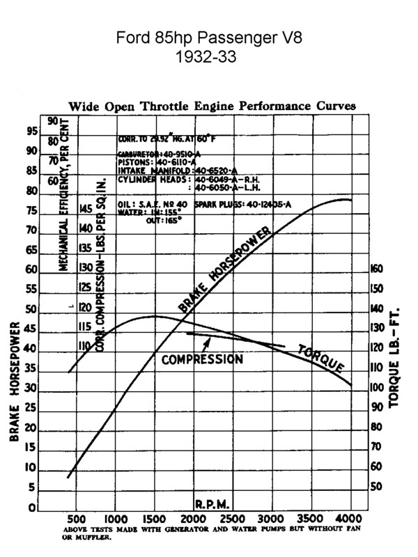
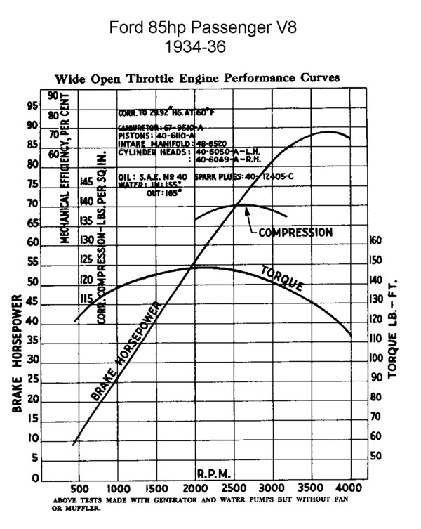
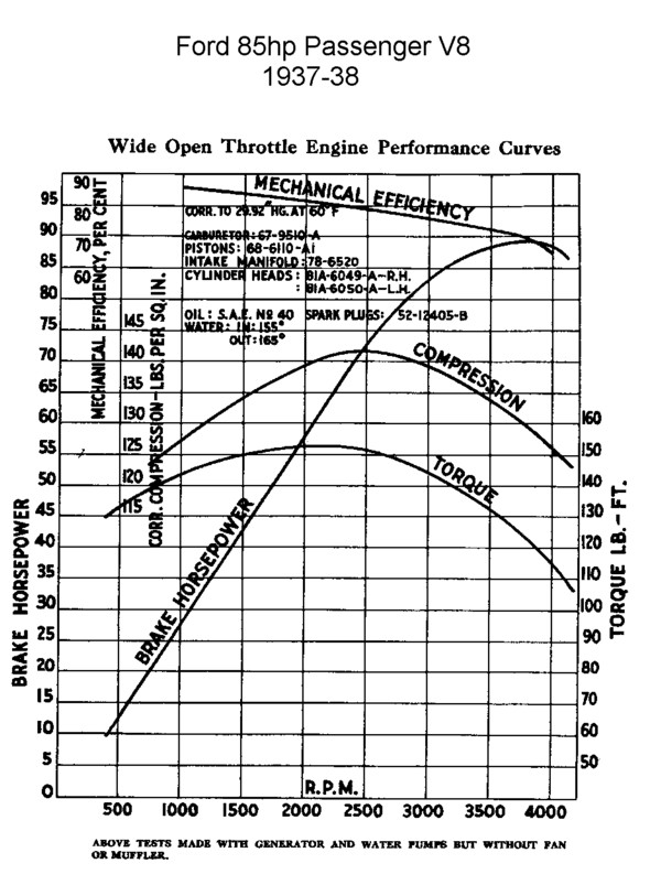
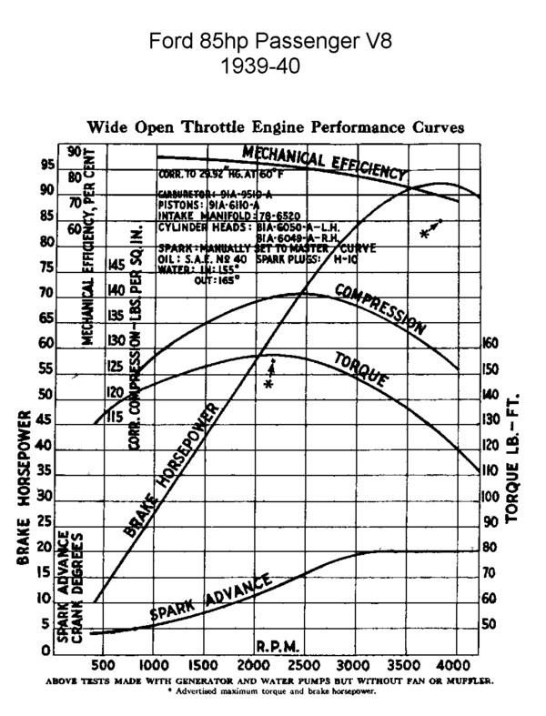
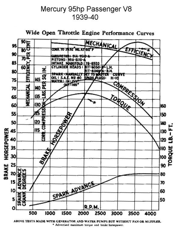
Horsepower & Torque Curves
Flathead_enginecurves_1932-33_85hp.jpg (122159 bytes)  Flathead_enginecurves_1934-36_85hp.jpg (114548 bytes)  Flathead_enginecurves_1937-38_85hp.jpg (123322 bytes)  Flathead_enginecurves_1939-40_85hp.jpg (132755 bytes)  Flathead_enginecurves_1939-40_95hp.jpg (128516 bytes)

Crack V8 Blocks

Cracked Blocks

The most common place for a crack is between the valve seat and cylinder. An old timer told me that you see more cracks on the intake side than the exhaust side because the metal is stressed by being alternately heated by combustion and cooled by the intake charge, but I don't know if it is true. Whether it is worth repairing these blocks depends on whether or not you can find both ends of the crack, how far it goes, and how many there are of them.
This is a typical valve seat to cylinder crack that you can see with your naked eye. Another common crack is seen on the right between the bolt hole and the water passage. Many flatheads have these bolt hole to water passage cracks and they can usually be ignored unless the crack runs to both sides of the hole. Some people plug or weld these cracks and some don't.
This is another view of the same cracks.
This is a bad repair job using plugs, I think. I don't see any threads where the block broke away as would be seen with a proper plug, and in real life, there is a bronzy cast to the repair making me wonder if brazing was used. I can't imagine that brazing wouldn't have melted away, but this engine had so many bad mechanic things in it, nothing would surprise me about it. I even found lead shot in the crank case.
The same engine with another bad repair. Neither of these repairs used sleeves and they clearly did not follow the cracks to their end. To be perfectly honest, I don't know how the engine ran except that it is hard to keep a flathead down. There were three easily visible cracks in this block and since I only got it for the Merc crank, I simply haven't looked closely for more nor has it been magnafluxed. Some things you just don't need to know.

Source:  http://flatheaddrag.com/cracks.html

'53 8RT truck engine and the '53 passenger car engine


About the only real obvious differences between the '53 8RT truck engine and the '53 passenger car engine are the exhaust manifolds, heads, and motor mounts. The dark wires behind the carburetor are loose wires attached to the solenoid which were just laying there when I took the top two photos.


My main hope for salvageable parts was the aluminum front cover. Ain't it purty? It's real light weight, too. This version doesn't have the bushing for the extension on the end of the distributor which is a good thing for me because the MSD electronic ignition system I want to use in my race car doesn't have the extension. I shoved the road draft tube back into its hole in the intake manifold for this picture.


You can see the freeze crack in the head in the photo above. It is dark because of the oil in the water jacket. The only way I know of for oil to get into the water jacket is a crack inside the block somewhere, usually the crank case, or for someone to add it to the coolant.


This view shows the rubber seal that fits between the block and the sheet metal front of the lower part of the bell housing to which the starter bolts. (Confusing enough for you?) You can also see the bulge in the pan which encloses the oil pump, the bulge in the block where the oil pump shaft fits, and the back cover over the oil pump drive system. The circle with the four holes in it is, of course, the end of the crankshaft.


I have taken to disassembling flatheads with an impact wrench these days. I have yet to break a head bolt since I started doing that. These head bolts came out way too easily. I discovered that they were well lubricated by what appeared to be crankcase oil in the water jacket. It isn't supposed to be there.
The first head I pulled was the engine's left head - the one that covers cylinders 5-8. It looked pretty good. The pistons were standard size and there was no significant ridge at the tops of the cylinders. My hopes were up.
The right side, cylinders 1-4, was a different story. My hopes went down. The rod sticking up is the fuel pump drive rod. Often these are worn with a flash on the bottom which makes them a little tough to extract. This one had very little wear and came right out.
Although the engine didn't look too bad inside, #1 and #2 cylinders were a mess. Rusty crumbles and mouse droppings filled the intake port and cylinder on #1, while #2 had this rust "pillow" which was a new one on me. There is rust pitting around the valves and transfer areas. You can also see the oily residue in the water jacket in the large lower coolant hole on the left edge of the picture. Hopes for survival are pretty low at this point.


Almost everything unbolts from this engine in a fairly straight forward manner except the water pumps. You have to know about the "secret" bolt. It is inside the housing at the end of the extension in this picture. I always imagine that getting this bolt out is going to be a horrific struggle and I am usually surprised at how easy it is most of the time. Well, maybe not THAT easy, but better than I expect. You can see the rusty pointer for timing the engine sitting in stark contrast on the aluminum front cover near the crankshaft pulley.
With the water pumps off and the timing gear cover off, it is easy to make out the truck motor mount. Every 8BA style flathead block I have ever seen has the bolt holes for the truck mount. You can see the aluminum timing gear which bolts to the end of the camshaft and meshes with the crankshaft gear which you can see behind the pulley. On early style engines, like 59As, the gear pitch is in the opposite direction so that the cam thrust is against the block. In late engines, the cam thrust is against the timing gear cover. Also visible just inside the water pump impeller openings are the end exhaust ports which, like all of the exhaust ports, go through the water jacket. The small holes at the top of the water pump mounting surface are not bolt holes. Rather, they are water passages which allow the water pumps to move some water around in the engine before the thermostats open. Some people plug these so that, after the engine is warmed up, hot water from the engine doesn't dilute the cooled water from the radiator. The medium sized holes below the big impeller holes have been a mystery to me. I think they must have had something to do with the casting process. Water pump gaskets don't have a hole for them. Of the two holes at the very bottom of the water pump mounting surface, one is a bolt hole and the other lets water into the pump's lower hose bib so the block can be completely drained by the drain cocks in the radiator.

Under this cover are the oil pump drive gears.
The gear on the right is on the end of the camshaft and comes out when the camshaft is removed. The big gear to its left is an idler which turns on a shaft fitted very tightly into the block. This gear and shaft should be removed from the block prior to rebuilding the engine. The gear on the oil pump is just barely visible on the left of the big gear.
Luckily, Ford provided a 3/8 inch threaded hole in the retaining shaft. There are pullers made for removing the shaft and gear, but I use a piece of hardened all thread which is screwed into the hole. The all thread is fitted with a nut and washer a comfortable distance away from the engine and the slide from a slide hammer is between the engine and the bolt and washer.
It is then necessary to find an old geezer to work the slide hammer. A few whacks and the assembly pops right out. I put down a sheet of corrugated cardboard (OK, it's a flattened out box) to catch the gear without denting it if the assembly comes apart on its way out. Can you tell that my garage is unheated?
If it stays together, it looks like this. The extension on the gear faces out.
Here are the two separate pieces.
The oil pump gear is clearly visible on the left.

This is it - flathead goo. Grandpa's 8RT may have been a little extra blessed by its years outdoors, but you can generally bet that every flathead has some pretty foul stuff in its pan, lifter valley, crankshaft, and any other nook or cranny where stuff can settle out of the oil.
The shape of the pan was a bit of a surprise to me since I expected to see a flat bottom with the famous truck pan clean out. Apparently, in '52 and '53 they didn't have them. Another style of rear sump pan is found on Mercurys. The Merc pan sump is shorter, but deeper. Ford passenger car pans from '49-'53 (or '54 in Canada) have center sumps. I suspect they all hold the same amount of oil.
The back end of the pan showing the lower half of the rope seal partially pulled out to help you see it, and the bulge on the picture's right, engine's left, is for the oil pump.
The front of the pan with the rope seal still in place. The baffle on the right help keeps oil from being blown out the road draft tube.


(No, not that one!)

With the pan and timing gear cover removed, you can see from the top, the spiral-grooved sleeve that the rope oil seal clamps against, an oil slinger, and the gear which drives the camshaft gear. The front main bearing cap is next. It looks pretty much like the center main bearing cap except that it has a little tit cast onto it which you can barely see before it slips into the shadow. The first two rods on the crank are #5 and #1. Don't ask me. It's just the way Henry did it. You can also see the camshaft's distributor drive gear in the back at the top of the picture
On the back half you can see the oil pump on the picture's right and the pickup screen on the picture's left. Notice how grandpa's oil screen is collapsed. I can only assume that it was clogged and the pump sucked hard enough to cave it in. I was amazed at the distinct flash from the casting molds on the crankshaft. A hot rodder would smooth these to prevent stress risers.
I don't recall seeing 8BA cast into '49-'51 Ford cranks, but I guess they didn't want to confuse anyone in the later years. EAB would be the markings on passenger car heads for '52 and '53. The 8RT truck engine used the same crankshaft. Also notice that the rods and rod caps are stamped with their cylinder number - 5 & 1 on the top two. The stamp is on the outer or downward side of the rod, depending on your perspective.

There are any number of tricks for freeing stuck pistons in an engine which has been sitting idle for a long time. Most involve putting a penetrating oil in the offending cylinder and periodically tapping it with a hammer handle or a 2x4 used as a drift. Some folks with the means to do so immerse the entire engine in a barrel of diesel fuel for a few weeks before starting disassembly. Grandpa's #1 and #2 were beyond any tricks I performed.
The ultimate approach is to beat, chisel, drill, saw, and/or grind out the offending piston and the rings. The rings are usually the real problem, being rusted to the cylinder wall. Be careful of the cylinder walls and rods if you plan to reuse the block or rods. Drilling out one half of the piston skirt, cutting through the rings in the process, and splitting the piston head in half usually frees it up enough to drive out. However, even though #1 came out that way, #2 had to be split down both halves and even then was hard to loosen up with a heavy hammer and drift. It may be hard to see in the photo, but in real life, when a piston is cut out like this it is easy to see how the wrist pin is offset in the piston rather than in the center. In this case, it is the right side of the engine so the wrist pin is offset away from the valves. This is why it is important to make sure the markings indicating the front of the piston are pointing toward the front of the engine during a rebuild.
With the piston driven down to loosen it up, you can see how much was removed from the piston. Notice how the upper half of the piston skirt broke off at the lower oil ring land exposing the steel piece embedded in the piston. (Could you follow that sentence?) Also, notice the aluminum chip "snow storm." What a mess this makes.
With most of the pistons, you can continue to drive them out the bottom, but not all. The center main bearing web interferes with #2. It would figure that the hardest one to get to move at all also had to be driven back up through the top. At least I was able to get the crankshaft out of the way.
Once the #2 piston was out of the way, a big crack was revealed. I drew a clumsy green loop around it to help you see it. I would guess it was caused by freezing water. Depending on what else turns up, a sleeve might save the day, but a real mechanic might have a different opinion. Regardless, it will have to wait until I'm a little more desperate for a block. Of course, I might just get sentimental.

This is the ubiquitous "pickle fork" flathead valve tool. It is used mostly to put the valve assembly back together since most valve assemblies I have run into are stuck to the block too tightly to move with this tool. However, it is handy for one phase of disassembly.
You will probably find that the valve locks are pretty well stuck to the spring retainers. It will make life easier if they are freed up before using a modern spring compressor to remove the valve locks. Just insert the tool under the spring retainers.
Then pry up. Unless the valve is frozen in the guide, the valve usually lifts instead of the desired action of the locks breaking loose from the spring retainers. Just tap the valve head with a hammer while lifting up on the tool and it usually breaks free. Note that these are the '52-'53 two piece spring retainers. Most hot rodders prefer to replace these with '49-'51 retainers and matching after market springs.
Now I can clamp on the valve spring compressor.
Use a screwdriver to flick the locks to the side. No sense in risking fingers on this.
Pry up the valve and remove it, then pry the spring and spring retainers out with a big screwdriver. Finally, drive the guide down from the top using a deep socket of the right size or a half inch extension so you don't mangle the hole in the guide or the block. Sticking out of the top of the spring on the left is a tab with a hole in it. This is part of one of the "C clip" valve guide retainers. More about that later.

That's it for now since this is as far as I've gotten to date and I'm out of pictures. I'll update with the rest of the process in the future.


Source:  http://flatheaddrag.com/gpf.html