
Ford tries to make a Point with a 1937 Ford Sedan
 |
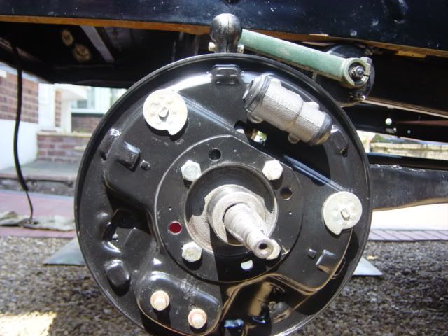
| Model A Spindle and Rear Brake |
 |
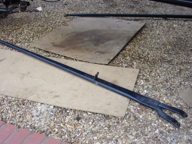
| Ford Model A Emergency Brake |
 |
| Front Spindle & Brake |
This subject seems to come up alot on the HAMB, "How do I fit hydraulics to my Model 'A' ". Hopefully this should show how to fit said brakes the CORRECT way.
My Model 'A' came already fitted with hydraulic brakes, but the more I studied them the more things I noticed were wrong with the way they were fitted. The true horrors weren't discovered until they were actually removed from the car.
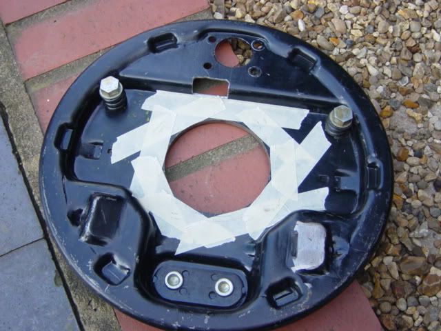
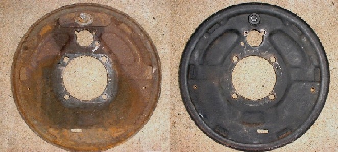
I decided the best way forward was to start again with a fresh set of backing plates.
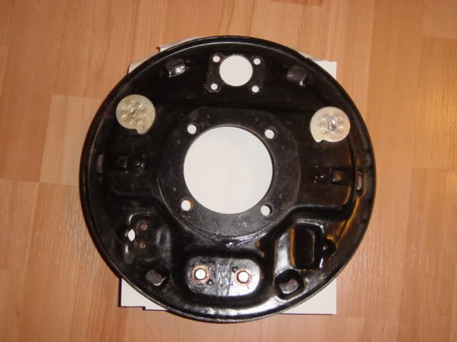
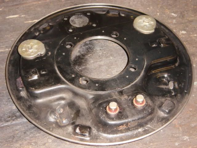
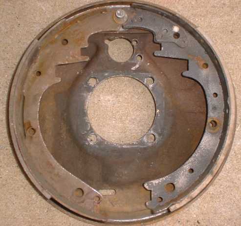
Here is your basic '39-'48 Ford backing plate. In this case they are the later '46-'48 plate as they have the riveted rather than bolted bottom pivots. You will also need the correct hubs and drums as the original 'A' ones will not work with the hydraulic backing plates.
We'll start with the fitting of the front brakes first.
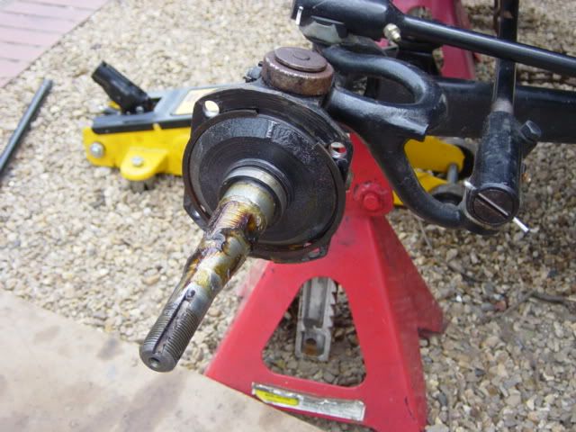
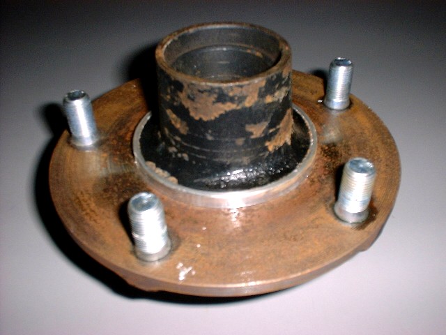
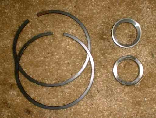
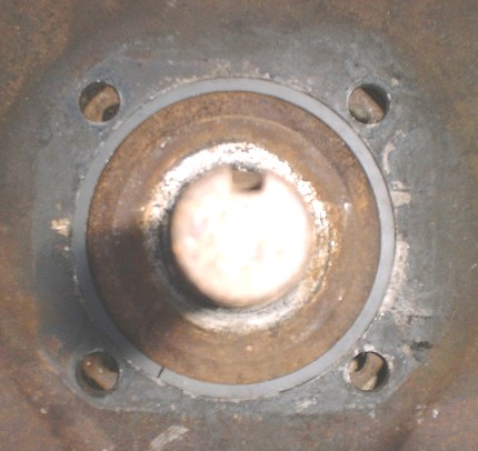
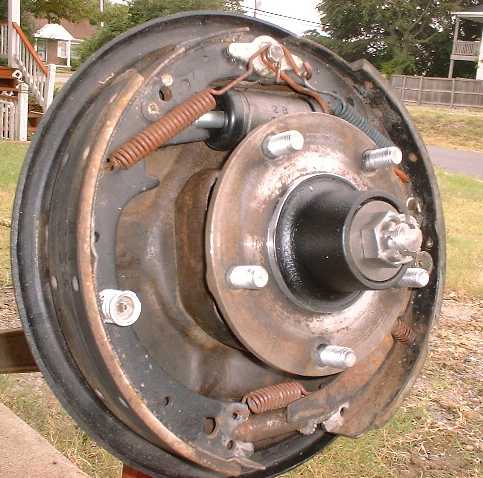
This is the stripped hub. You'll need a front fitting kit which consists of 2 bearing spacers and two backing plate spacer rings. You can see how these are mounted to the hub.
Take care with the backing plate spacers as they are cast iron piston rings and will break easily if forced.
The Model 'A' has a smaller backing plate stud spacing.
There is two ways you can approach this:
1. Elongate the original hole in the backing plate.
2. Plug the original holes and re-drill them for the Model 'A' stud pattern.
I choice the second as I believe this to be the correct way.
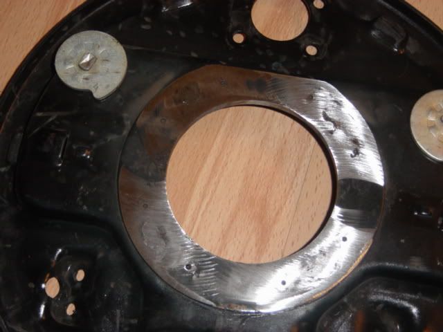
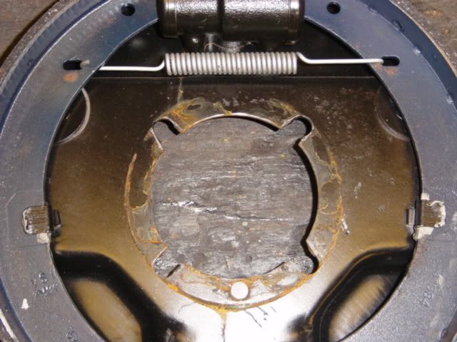
You can see in the above picture the now hole-less backing plate. A plug was cut from 3/8" steel rod and then plug welded both sides and ground smooth making sure not to remove material from the mounting surfaces.
Now is time to re-drill the mounting holes.
You can get complicated here and have it all set up on a rotatory table on a mill or do what I done and just mark it from the back!
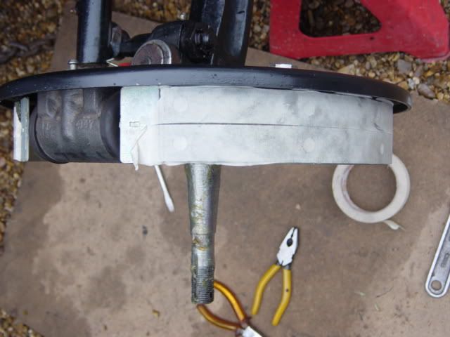
The backing plate was masked with tape and placed on the hub.
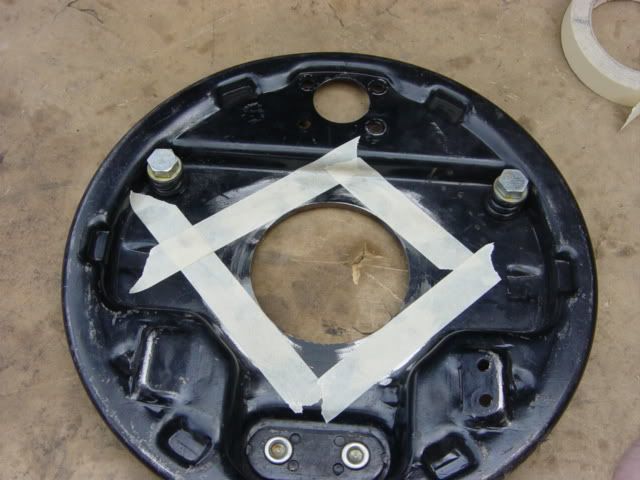
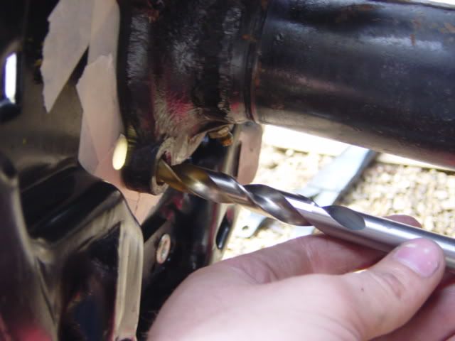
With the backing plate mounted to the hub, making sure that the wheel cylinder is at the very top on the vertical, mark the position of the holes with a 3/8" drill bit, this will be your final hole size.
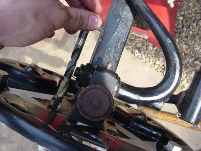
Use a drill press as this way you will have a nice straight hole. You should find that the backing plate sits flat making it easy to clamp down.
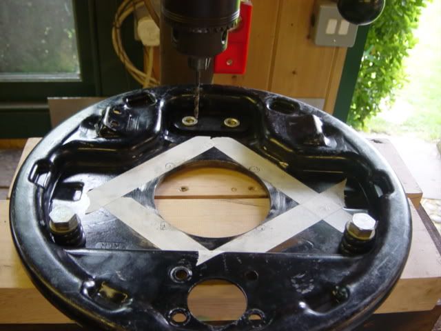
Use a small 1/8" pilot drill hole, double check everything and then keep enlarging the holes until you finish with a 3/8" hole.
If you find that its gone wrong somewhere, simple plug weld the hole and start again.
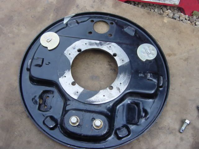
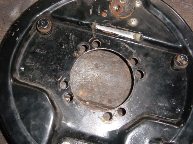
The finished article. Notice how close the holes are to the edge? Thats just the way it is I'm afraid.
QUESTION: Don't take this the wrong way. It's a great post. I am concerned about the lack of edge distance between the center of the hub and the mounting holes(which you already mentioned). I know it is a limiting factor because of the diameter of the spindle, but the way you have your holes drilled is really not much stronger than the ones you showed as the bad example. I wonder if you could add a doubler on the inside to help displace some of the load? Like a circular ring?
ANSWER: The backing I used actually has the reinforcing spacer ring you mention. They came from the factory like this and I believe they are from an F3 truck. The difference between mine and the bad ones shown is that mine are securely located. The slots in the bad example are so inaccurate and sloppy that the backing plate had the opportunity to move on its mounting when fitted to the car. Done properly with a single hole it doesn't matter where you apply a force on the backing plate it can not move. I don't think there is a stength issue here.
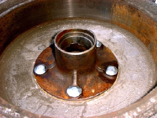
If everything is correct it should all bolt up.
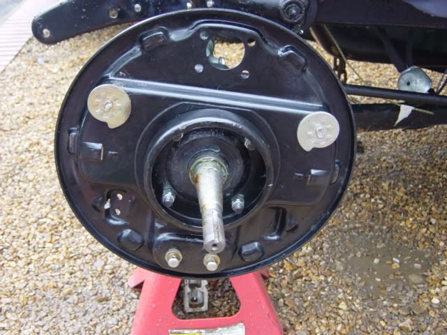
Complete the assembly of the brakes and its job done.
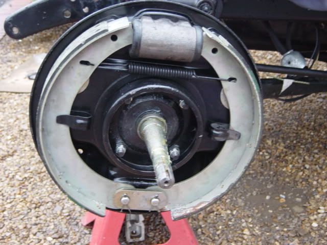
A little tip when assembling the brakes is to cover the shoes in masking tape. This stops the shoes getting covered in grease, oil and God knows what else.
That completes the front brakes and finally an example of how not to do it. Yes these are what were originally fitted to the car.
Rear Brakes
Moving onto the rear. This becomes a little more involved and will need machining to do it properly.
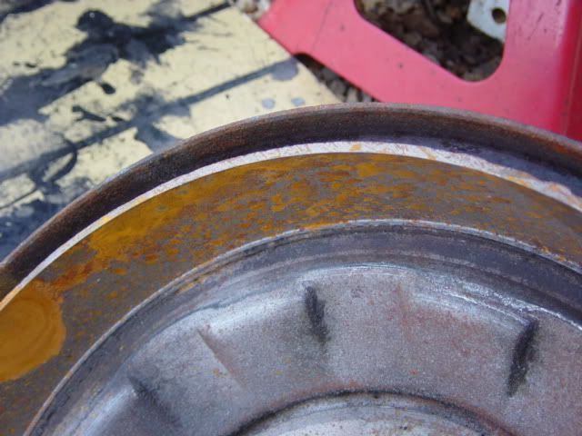
First off is the very outer edge will need 1/8" machined from it.
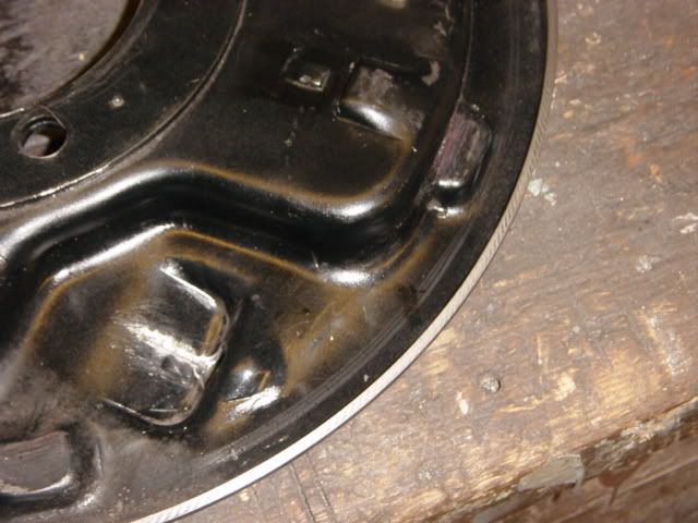
Also 1/8" will also need to be removed from the back of the rear drum.
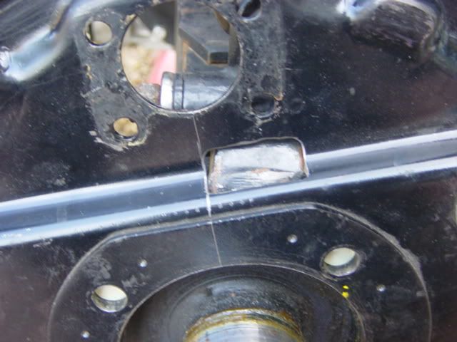
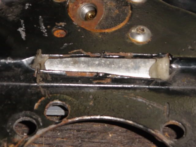
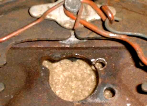
The backing plate will sit on the rear axle casings and the holes will line up. You will notice that the backing plate will not sit flat because it will clash with the spring hanger.
The way to remedy this is a small clearance slot in the backing plate, as below.
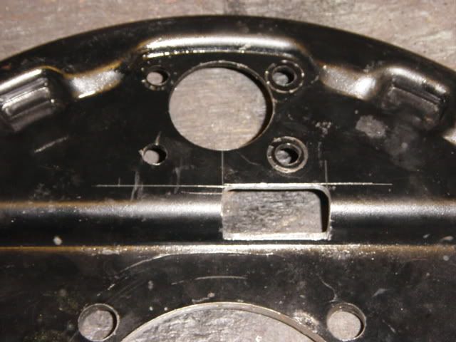
For best results it will best have these machined on a mill as I had mine done. I would think a similar result could be achived with a angle grinder.
Comment:
A very good post regarding the 40-48 front brake swap for Model A's...I love these cars, and have 7 in my collection...But there's a few things I learned over the past 34 years. My two cents worth regarding the rear brake backing plates. I didn't like the idea of making the "window" cuts in the backing plates.
I removed the wheel cylinders and to take care of the interference with the spring mount perch, I heated the area red hot with the torch and forged a dimple so I wouldn't have to cut the two windows. This way there's less open to the weather and dirt.
Another thing I did. I did this adaption in 2001 when I had the rear end torn down for some work. I had a machinist friend with a big lathe cut 3/16" off the face of the mounting flange on the rear end housing for the backing plates. That cost me $20. This pulled the backing plates in so I wouldn't have to use shims to space out the hub. In your case you trimmed the brake drums. Either case it involves some machining to effect the same result.
I found thru the years that using the shims didn't work well for me, as they wore out every year, and I was always replacing them and the keys. Luckily I kept ahead of this on a yearly basis and didn't screw up my hubs or axles. I gleaned this info from California Bill's book on the Model A....I found a reprint of this 1952 book in a bookstore for $5! This saved me the yearly inspections and replacement of shims and keys. Nice article.
The following is the drawings to show where these slots will be in the backing plates. Remember that they will be handed.
Right rear.
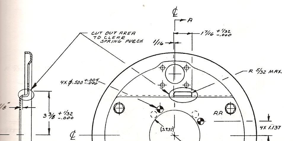
Left rear.
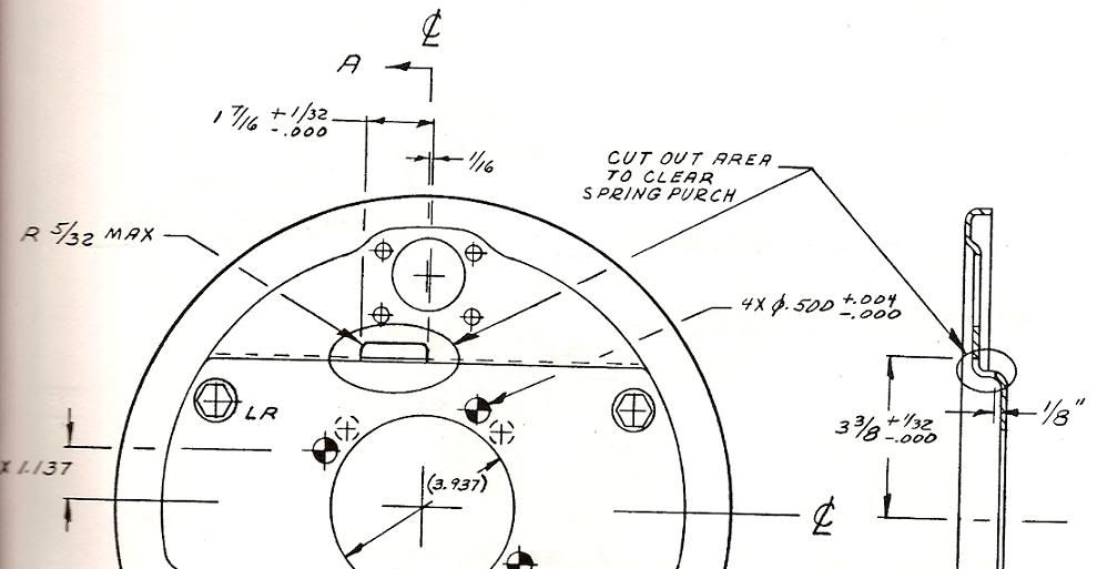
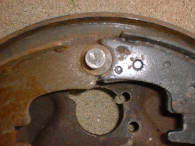
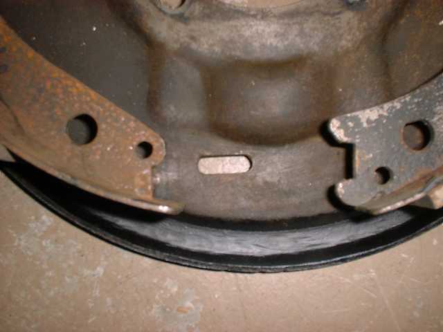
With the slot the backing plate will now sit flat on the axle casing. Notice in the picture how the spring hanger now sits flush with the backing plate.
The second problem your now going to experience is that the wheel cylinders also have clearance problems with the spring hanger.
The way to overcome this is to rotate the backing plate forward. For reference the recommended number of degrees is 16. I found this not to be enough so I just rotated the backing plate until I had adaqate clearance with the wheel cylinder and more importantly enough space for the brake fitting and pipe.
With the backing plates held in position it was the same process as the front in marking the holes.
I used a 1/2" drill bit as this is the final hole size.
I removed the rear wishbones to make it easy to mark the holes.
[img][/img]
Again the backing plates were drilled on drill press. You can plug the original holes but I chose not to.
Your final hole size 1/2".
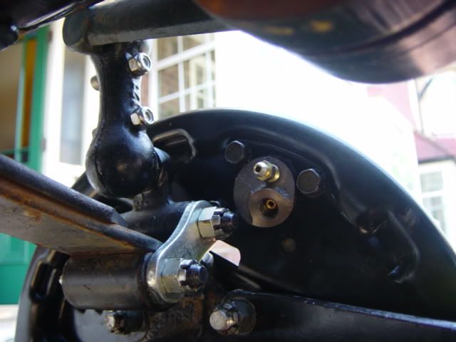
With the rear backing plate mounted with a wheel cylinder you can see the amount of rotation. I kept the rotation to a minium to try and keep the wheel cylinder as high as possible.
If you look closely you can see how with the extra rotation of the backing plate how the clearance slot has moved round.
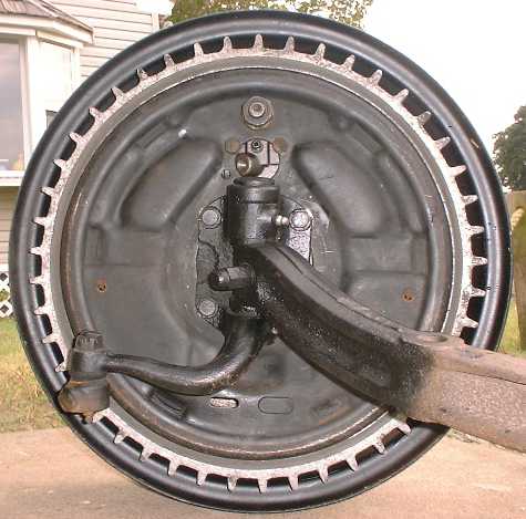
A shot from the back.
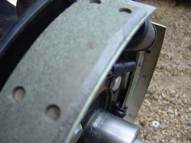
Before final assembly of the rear brakes you want to put a large chamfer on the outer edge of each brake shoe. This is because the shoe will rub on the inside of the brake drum.
Again some examples of how NOT to do it.
Apart from the obvious poor workmanship here the new mounting holes were actually drilled the wrong way so the backing plates rotated back not forwards. this had cause all sorts of problems with plumbing the brakes
Some final information.
When you tighten everything up you may find the drum binds. This may be due to wear on the tapers.
If this is the case you will need some axle shims. The car came with 2 but I found I needed just the one, the fewer the better in my opinion.
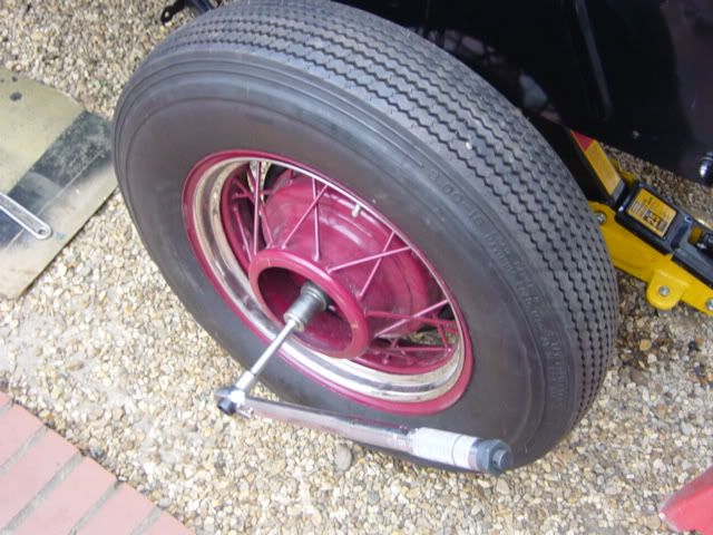
To finish you want to torque the nuts up to 80-90 foot pounds. this is important as its the taper NOT the key that holds the hub to the halfshaft. I find it best to put a wheel on the car and then torque the nut as this stops the drum from spinning.
QUESTION: Good work. Three comments/questions. (meant as constructive criticism, not nit-picking.)
1, The 80-90 lbs feet figure is surely too low.
I've read figures of 200-220 quoted, plus regular retightening and further tightening to the next castellation. (dont exceed 275 ft lbs) I think if anyone follows the 80-90 lbs ft figure they'll have trouble.
2, if you knew about the rotation before cutting the clearance slot in the rears, would you have made the cut out slightly different.?
3, Do you think they'll bleed ok with that much rotation? I'm not saying they wont, I just wondered if this is an established method, and people have tried it before and it's ok.
4, Is it not an established technique to use the rear backplates upside down? This just rings a bell from somewhere, I've not tried it myself. That would keep the cylinder and the backplate ridge clear of the spring mount. Anyone else seen it done this way?
You'd have to fit the cylinders the right way up of course so they would bleed ok.
Keep up the good work. Nice documentation and presentation, glad to see you're doing the car right.
ANSWER: No problem, if there something wrong I would rather know than cause problems to myself or someone else.
I've checked three different publications and now have three different torque settings!
The first is the 80-90 ft lbs the second is a larger 125 ft lbs and the third says tighten well!
I'll look into it further.
Of course if I'd known about the position of the slot I would have done it differently.
They have already been bled and are fine. Even though the backing plates have been rotated the wheel cylinders are still the highest point.
Yes, you can mount the backing plates up-side down. I personnely don't like this way as it puts the wheel cylinder very low, which may cause problems with bleeding the system. Also the brake line will run very low leaving it vunerable to being damaged.
Source: http://www.jalopyjournal.com/forum/showthread.php?t=124112&highlight=model+brakes
Appendix:
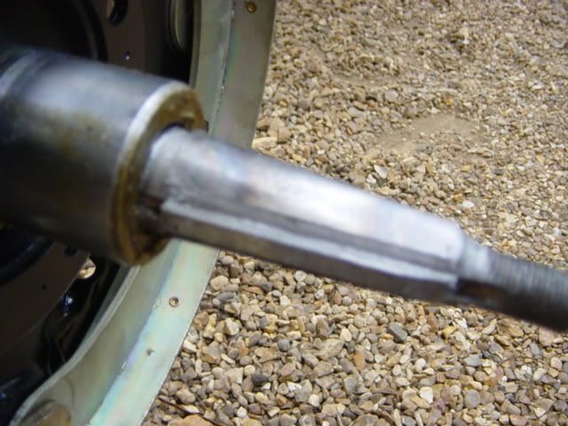
These shots show Wilson Welding 1939 Lincoln backing plates adapted to Model A spindles. First pic shows that the center hole in the backing plates is too big for the A spindle. The 4 mounting holes are not where they need to be.
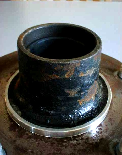
The second pic shows a piece of 4" pipe turned down in the lathe to make the spacer. You can get valve seats to add to the spindles for the grease seal to ride on.
The magazines suggest wallowing out the mounting holes with a file but you can do better.
The third pic shows the spacer welded in, the mounting holes welded shut and new holes drilled. For 1937 to 48 spindles, the backing plates bolt up and no adapters are needed.
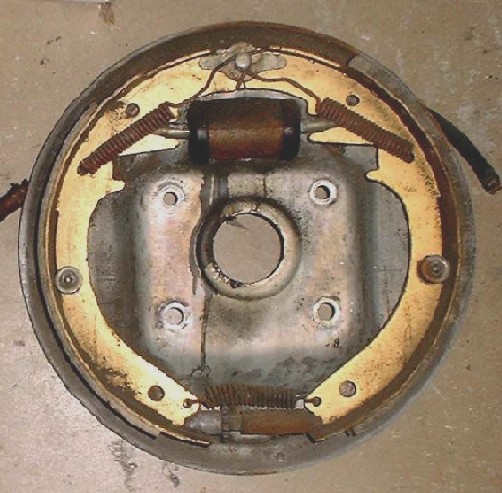
The fourth pic shows the assembled brake complete with the self adjusting parts. The brake shoes are 12" by 2" for 1976 Chev Big Station Wagon rear wheel brakes. The wheel cylinder is a 1 1/8" front from a 1964 F-250. (The 1/2 ton has 1 1/16") The bigger wheel cylinder gives more of a 'power brakes' feel.
The brake drum used is 1940 Ford. Henry put 1 3/4" shoes in these drums but they are more than 2" wide. You get more swept area using ALL of the drums usable surface.
The self adjusting parts are also from the 76 Chev 12" brakes. If you dont have the self adjusting arm for 12" shoes, you can get all you need from the more common El Caminos and other Chevys from the 70s. The springs and all the small parts are the same, cut and weld to extend the adjusting arm to fit 12" shoes.
There was a magazine article recently promoting the Lincoln brake kits for more than $3000! and those brakes are not self adjusting. The article does not state how wide the shoes are in that expensive kit.
Bob Wilson charged $150 for the backing plates, the shoes were $13.88, the wheel cylinders were $11.88, the small parts kits was less than $5, turning the 1940 drums was $7.50 each, and I got new star wheels, they are inexpensive too. The 1" master cylinder (I used 77 Thunderbird) was about $30, A new 20' stick of stainless steel tubing cost $18 and a dozen Stainless brake line fittings are $2 each. (Advance Auto wanted $2.65 each for mild steel fittings)
Total is less than $300 for the front brakes, master cylinder and all the stainless brake line and fittings. Cost of wheel bearings, races and seals is not included in the $300. The original Model A wheels still fit as do all 5 on 5 1/2 wheels.


Source: http://www.jalopyjournal.com/forum/showthread.php?t=124317
Buick Conversions
There is a ton of good stuff on the HAMB about Buick drum/hydraulic brakes but no single post on the complete conversion. I just finished up the front brakes on my 29 and figured I would do a write-up on the “how to” and parts I used to tie it all together. I apologize for having links to some of the pictures, but their is a 20 picture limit on posts.
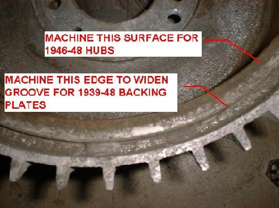
Unless you are prepared for a lot of headaches and stuff that doesn’t fit together, an old Wagner or Bendix brake parts interchange manual is a must have. I started with a set of 45-fin Buick 12” aluminum drums from a 1964 LeSabre, a set of 1953-56 F250 backing plates, early Ford 1943-45 juice hubs that mount on the INSIDE of the drums, and 1935/36 spindles and axle. The 45 fin aluminum drums were used in big Buicks from 1957-64. The F250 backing plates are the Bendix floating/self adjusting design similar to the hard to find Lincoln backing plates, a huge improvement over the 1939-48 Ford-Lockheed brakes. I went with the 1943-45 hubs because I planned to run 16” smoothy rims with a 5 x 5 ½” bolt pattern. There is a little less machining if you use the later 1946-48 hubs instead of the early Ford 1939-42 drums/hubs. I considered using my original Model A hubs but never heard of anyone using them and given the low speed design of these cars, I didn’t want to be the first to try. I picked up 1935/36 spindles/axle as cheap way to lower the front end of the Model A with the stock 2” drop axle.
http://www.sunbunnybrown.com/details...MB/spindle.jpg
In addition to the 1964 LeSabre drums I was using for the conversion I also had a 1960 Invicta drum. They are the same thickness, diameter and have the same size hub register hole, but there are subtle differences between the early and late Buick drums. The LeSabre drums had balance weights and the Invicta drum did not. The machined area for the hub on the inside of the drum is about 1/8" smaller in diameter on the early drum and may require machining a little too close to the bolt circle for inside the drum hubs. There are also several differences between the two drums to accommodate the linings used in the two cars. The 1964 LeSabre drum has a 2 ½” wide machined surface to accommodate 2 ¼” wide shoes and the lining contact surface is recessed ½” from the back of the drum. The Invicta drum has a 2 ¾” wide machined surface to accommodate 2 ½” wide shoes and the lining contact surface is recessed ¼” from the back of the drum. Using the early drums will effectively move the drums inboard, a clever way to avoid spacers that may be needed to bring the linings in full contact with the drums for certain combinations of backing plates and spindles.
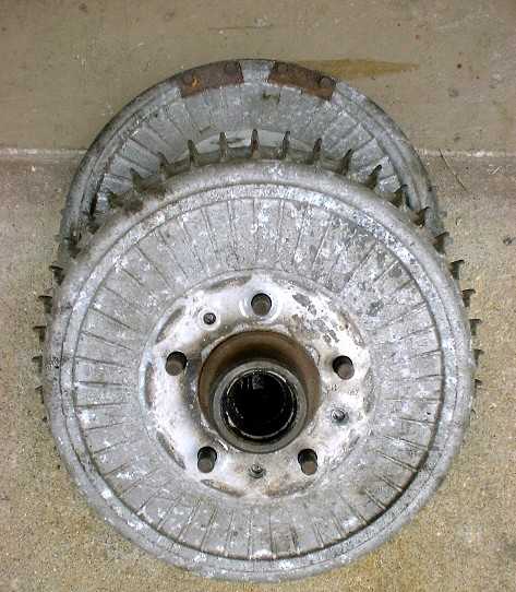
I drilled out the rivets on the Buick drums and knocked out the studs on the Ford drums to separate the drums and hubs. Be careful to support the backside of the Ford hubs when you knock out the studs so you don’t bend the mounting flanges!
A buddy of mine did the machine work to register the Buick drums to the Ford hubs. He had hoped to find a chunk of pipe that was close to the right size to make the job a little easier but ended up using aluminum stock. The drums should be registered to the hubs, NOT the studs, so you don’t need to be concerned about the orientation of the drums and the hubs in the future.
After cleaning up the snouts on the Ford hubs, he bored a hole in the aluminum stock for a light press fit on the hubs, then turned the ODs for a tight slip fit to the holes in the Buick drums. He trued up the mating surfaces of the Buick drums and the Ford hubs and turned the OD of the hub flanges to fit the recesses on the inside of the Buick drums. The register rings were installed with Loctite Spherical Parts Locker. I am running 16” steelie wheels so I wanted to keep the 5 ½” Ford bolt pattern. Pilot holes were drilled in the Buick drums to match the pattern with the final sizing waiting until the studs were installed so the holes could be machined for a nice slip fit.
http://www.sunbunnybrown.com/details...MB/hubBack.jpg
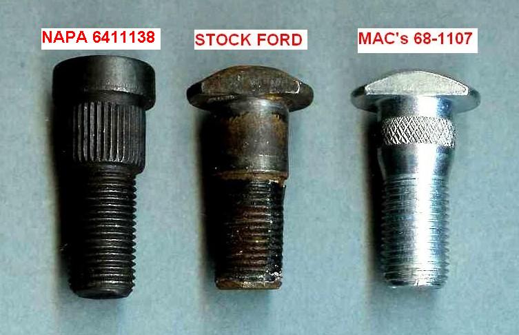
I had used a BFH to knock out the Ford studs and the Buick drums were ~3/16” thicker than the original Ford drums so new longer studs were needed. I have seen suggestions to use NAPA 6411145, 6411138 or Dorman 610-132 studs. At 1 29/64” overall, the NAPA 6411145 may be a little short for good lug engagement, and all of these studs are larger in diameter than the originals and require machining the holes in the hubs. You can get original style studs from Mac’s for about a buck and a half (Mac’s 68-1107). At 1.56” overall (original studs were ~1 3/8” overall), the studs were plenty long to use with the Buick drums (six full threads of engagement with 16” Ford rims). They were a little loose in hub bores so we knurled them and installed them with Loctite Spherical Parts Locker. After the studs were installed, the holes in the drums were machined to their final size.

http://www.sunbunnybrown.com/detailshop/HAMB/assy.jpg
Speedway and Mac’s sell kits that include backing plate centering rings and spindle shaft spacers for mounting juice backing plates to early mechanical brake spindles (Speedway # 91631928 @$19.95 and Mac's #X-2000 @$17.95). I have been told that you can use Model A piston rings and valve seats but decided to spring for the $20 kit.
As it turned out, the spacers were not needed with the 1935/36 spindles I was using, 1937-41, round back or 1942-48 rectangular back spindles. Spacers or shortening the backs of the hubs would be needed with Model A spindles and the nearly identical 1932-34 spindles so the hubs do not bottom out against the backing plates. The rear bearings in the 1943-48 hubs are recessed ~3/8” and the rear bearing surface of Model A and 32-34 spindles is ~5/16” inboard compared to 1936-48 spindles. Careful measurements and the appropriate spacers/machining are needed with these spindles to ensure that the shoes are in full contact with the drums.
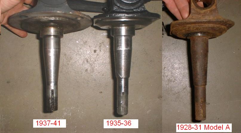
I showed in my original post as 35/36 are actually 36 only. The two are nearly identical with rectangular backs, large backing plate centering hole and 3/8” bolt patterns. The 35's have a long shaft like the ones used on the Model A’s and 32-34s, but the 36’s have the short shaft common to the later spindles. You would need the centering ring and spacer with the 35 spindle, but only need the centering ring with the 36. I don’t have pictures of a 35 spindle but here's a photoshop to see the difference:

http://www.sunbunnybrown.com/details...MB/BPslots.jpg
http://www.sunbunnybrown.com/details...MB/BPbolts.jpg
The F250 backing plates use single-sided wheel cylinders but are easily converted to dual cylinders by drilling an additional mounting hole. Most folks use F100 cylinders (1 1/16” Wagner #F41718/F41719). I did a little poking around on the Bendix website and found some whopping big 1 3/16” cylinders from a 1992 F250 Supercab that were a direct drop in for the backing plates. The bigger cylinders provide a little extra hydraulic force to the front wheels and the only difference was that they used a smaller 3/8” fitting instead of the typical 7/16.
I wanted to take full advantage of the F250’s Bendix brake design and robbed the adjusting hardware from the rear of the 1964 LeSabre 45 fin drum donor. You can also use the rear hardware from a 1971-76 Caprice Wagon with 12” drum brakes that is still available from GM.
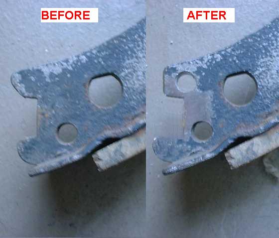
Things started to get tricky when I looked into the brakes shoes. Not taking the steps to ensure correct relationship between the brake linings and the drums has undoubtedly been the cause of many poor performing conversions. Mismatched spindles, spacers, backing plates and hubs could leave you with less than 1” of usable lining width!
The stock F250 backing plates used 2” wide shoes but the Buick drums can handle up to 2 1/2” linings. I mocked up the 2 ¼” and 2 ½” Buick brakes and the half round cutouts at the top of the shoes were machined differently throwing the shoes way off center (the Buick pivot pins are ~1/4” closer to the edge of the backing plates). I try to avoid modifications to service parts whenever possible and went with the 2” F250 shoes so I wouldn’t have to machine the critical pivot pin radius. I drilled 9/32” diameter holes in the bottoms of the shoes for the Bendix self adjuster springs and tweaked the slots in the shoes to improve the fit of the self adjusters.
http://www.sunbunnybrown.com/details.../brakeAssy.jpg
If you have your heart set on the larger 2 ¼” and 2 ½” shoes, it might be easier to modify a set of the early Buick 12” backing plates. You can get the spacers you need for the swap from Mecutem on the HAMB and has Pete Smythe psmythe@patrons.com has adapters and machined Buick backing plates for $200 plus shipping. Lots of good info in this thread:
http://www.jalopyjournal.com/forum/s...882&&showall=1
The outer lips of the F250 backing plates are ~3/8” wider in diameter than the 1939-48 Ford and Lincoln parts, and just fit inside the grooves on the backsides of the Buick drums. Keeping with my philosophy of avoiding modifications to service parts, I used a 4 1/2" electric angle grinder with a grinding wheel and thinned the lip by carefully removing ~1/16” from the inner edges of the outer lips of the backing plates for better clearance in the grooves on the backsides of the drums. I also machined an access hole for the self adjuster of the left hand backing plate. The F250 plates are not left and right and a new hole was needed to line up with the star wheel of the adjuster.
http://www.sunbunnybrown.com/details...justerHole.jpg
The early Ford juice and Lincoln backing plates require machining of the inner lips of the grooves in the Buick drums to accommodate the outer lips on these backing plates. If you are using the later 1946-48 Ford hubs that mount on the OUTSIDE of the drums, the thicker face of the Buick drums will move the drums inboard requiring a bit of machining to the top surfaces of the inner lips of the grooves in the Buick drums. If you plan to use these backing plates or hubs, you will have to mix and match these modifications so the backing plates clear the drums.
Careful measurements are required to ensure full contact between the linings and the drums. The offset of the F250 backing plates provides full contact between the 2” linings and the Buick drums, but this is not the case with the 1939-48 Ford backing plates. The shoe anchor pads of the early juice plates are offset ~7/16 “ inboard compared to the F250 backing plates. I have heard that some folks simply machine away a portion of the linings so the back lips of the drums don’t cut the shoes. The linings for these backing plates are only 1 ¾” wide. With a little more effort, you can correct the offset rather than sacrifice lining width.
Using 1946-48 juice hubs that mount on the OUTSIDE of the drums will move the Buick drums inboard ~3/16”, the difference in thickness between the original Ford and Buick drums. Using the early Buick drums designed for the larger 2 ½” brakes will effectively move the drum inboard ¼” compared to the later drums designed for the 2 ¼” linings. I have not mocked up either of these combinations, but it looks like this may be all that is needed to bring the shoes into full contact with the drums. Spindle/backing plate spacers can be fabricated as needed to move the backing plates outboard. The grooves on the backside of the Buick drums will have to be machined accordingly to accommodate the offset. Measure carefully and do whatever you have to do to ensure full contact between the linings and drums for the parts you have.
I do not have any Lincoln backing plates and can’t say how the offset of these plates affects lining/drum contact. Can somebody chime in on this?
Here are a couple shots of how everything went together. About ¾” of the finned drum is visible beyond the inner bead of the 4” wide 16” steelie wheels.
http://www.sunbunnybrown.com/details.../BPrearRim.jpg
http://www.sunbunnybrown.com/details...drumOffset.jpg
There are many combinations of spindles, hubs and backing plates that can be used for the Buick drum conversion, but just getting the pieces to bolt together doesn’t guarantee that they will function as an effective brake drum assembly. I think I have identified everything you’ll need to watch out for if you try the swap. Now if I can only get the time to slip the new axle under the A…
Source: http://www.jalopyjournal.com/forum/showthread.php?t=122603


Comment:
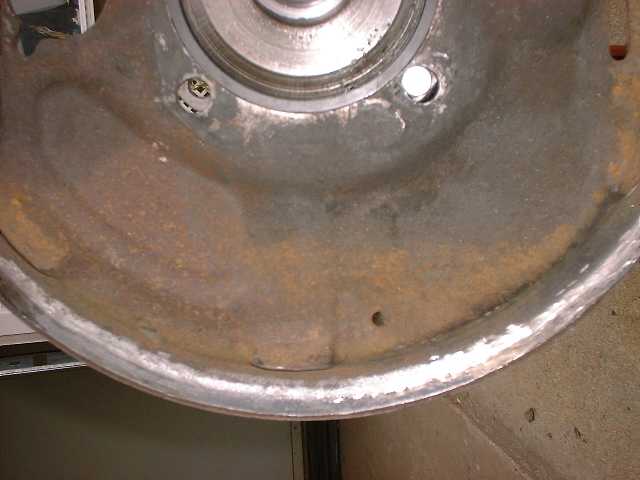
With the F-250 backing plates, if you use the '40 style hubs where the drum mounts on the outside of the hub, you should not have to trim any of the lip of the drum as shown in the attached pictures of a Buick drum on a '40 style hub.
If you mount the drum on the inside of the '48 style hub as normally done when using the Lockheed brakes you will have trim both the aluminum and the iron drum liner and with the rough measurements I made in the past, it seemed like there was not enough metal "above" the groove to allow the depth of cut needed.
If you compare the difference between the pieces of steel clamped to the hubs, in the the one picture, it should give you an idea of the difference in drum spacing between the the two style of hubs.
Comment:
The 40 hubs must be machined down on the OD to fit in the bottom of the cone shape of the center of the Buick hub. The pictures of 48 hubs would show the hub hanging over the edge of the drum. Cutting the hub means the outer support on the wheel is not making contact with anyting as the drum is angling away. 40 hubs can be drilled for the small patern but must be spotfaced as the surface is angled. I am very much concerned with folks trying to use the 40 hubs and not knowing the problems. The spacing is off in every dimesion stack I have done so it is possible but difficult to get the drum to cover the shoes completly. I have seen assemblies on cars where you could look down at the drum and see the shoes.
Question:
What if you are wanting to run 40 hubs with the big 5x5.5 pattern, 40 backing plates and spindles and 66 Buick drums? Is it better to run the 40 hubs or the buick hubs?
Answer:
I would only run the 46-8 hubs.The buick drum does not have a big enough mounting surface to contact the outer support nubs on the Ford wheels. The 46-8 hubs are considerably bigger in diameter. You could make a support plate that was the reguired diameter to support the wheel and put it on the outside of the drum. The 40 hub would still have to be greatly reduced in diameter to go inside the Buick drum. The new support plate would only be clamped at the inside and would need to be pretty thick. The whole thing is not as nice as using the 46-8 hub
Comment:
Thanks for the help Andy.
Ended up going with the 40 hub. And yes, we had to machine the hub down just a small amount and made a sleeve to locate the drum on the hub.
Yep, after looking at it, we made a 8" dia spacer to run on the outside of the drum to support the wheel. Hopefully I will get to putting it all back together this weekend. We will see, our new 3 week old son seems to keep distracting me

One side on, one to go... well, and get the finished spacers.

Source: http://www.jalopyjournal.com/forum/showthread.php?t=122603&page=2
No comments:
Post a Comment