About the only real obvious differences between the '53 8RT truck
engine and the '53 passenger car engine are the exhaust manifolds,
heads, and motor mounts. The dark wires behind the carburetor are
loose wires attached to the solenoid which were just laying there
when I took the top two photos.
My main hope for salvageable parts was the aluminum front cover.
Ain't it purty? It's real light weight, too. This version doesn't
have the bushing for the extension on the end of the distributor
which is a good thing for me because the MSD electronic ignition
system I want to use in my race car doesn't have the extension. I
shoved the road draft tube back into its hole in the intake manifold
for this picture.
You can see the freeze crack in the head in the photo above. It is
dark because of the oil in the water jacket. The only way I know of
for oil to get into the water jacket is a crack inside the block
somewhere, usually the crank case, or for someone to add it to the
coolant.
This view shows the rubber seal that fits between the block and
the sheet metal front of the lower part of the bell housing to which
the starter bolts. (Confusing enough for you?) You can also see the
bulge in the pan which encloses the oil pump, the bulge in the block
where the oil pump shaft fits, and the back cover over the oil pump
drive system. The circle with the four holes in it is, of course, the
end of the crankshaft.
I have taken to disassembling flatheads with an impact wrench
these days. I have yet to break a head bolt since I started doing
that. These head bolts came out way too easily. I discovered that
they were well lubricated by what appeared to be crankcase oil in the
water jacket. It isn't supposed to be there.

The first head I pulled was the engine's left head - the one that
covers cylinders 5-8. It looked pretty good. The pistons were
standard size and there was no significant ridge at the tops of the
cylinders. My hopes were up.

The right side, cylinders 1-4, was a different story. My hopes
went down. The rod sticking up is the fuel pump drive rod. Often
these are worn with a flash on the bottom which makes them a little
tough to extract. This one had very little wear and came right out.

Although the engine didn't look too bad inside, #1 and #2
cylinders were a mess. Rusty crumbles and mouse droppings filled the
intake port and cylinder on #1, while #2 had this rust "pillow" which
was a new one on me. There is rust pitting around the valves and
transfer areas. You can also see the oily residue in the water jacket
in the large lower coolant hole on the left edge of the picture.
Hopes for survival are pretty low at this point.

Almost everything unbolts from this engine in a fairly straight
forward manner except the water pumps. You have to know about the
"secret" bolt. It is inside the housing at the end of the extension
in this picture. I always imagine that getting this bolt out is going
to be a horrific struggle and I am usually surprised at how easy it
is most of the time. Well, maybe not THAT easy, but better than I
expect. You can see the rusty pointer for timing the engine sitting
in stark contrast on the aluminum front cover near the crankshaft
pulley.

With the water pumps off and the timing gear cover off, it is easy
to make out the truck motor mount. Every 8BA style flathead block I
have ever seen has the bolt holes for the truck mount. You can see
the aluminum timing gear which bolts to the end of the camshaft and
meshes with the crankshaft gear which you can see behind the pulley.
On early style engines, like 59As, the gear pitch is in the opposite
direction so that the cam thrust is against the block. In late
engines, the cam thrust is against the timing gear cover. Also
visible just inside the water pump impeller openings are the end
exhaust ports which, like all of the exhaust ports, go through the
water jacket. The small holes at the top of the water pump mounting
surface are not bolt holes. Rather, they are water passages which
allow the water pumps to move some water around in the engine before
the thermostats open. Some people plug these so that, after the
engine is warmed up, hot water from the engine doesn't dilute the
cooled water from the radiator. The medium sized holes below the big
impeller holes have been a mystery to me. I think they must have had
something to do with the casting process. Water pump gaskets don't
have a hole for them. Of the two holes at the very bottom of the
water pump mounting surface, one is a bolt hole and the other lets
water into the pump's lower hose bib so the block can be completely
drained by the drain cocks in the radiator.
 Under this cover are the oil pump drive gears.

The gear on the right is on the end of the camshaft and comes out
when the camshaft is removed. The big gear to its left is an idler
which turns on a shaft fitted very tightly into the block. This gear
and shaft should be removed from the block prior to rebuilding the
engine. The gear on the oil pump is just barely visible on the left
of the big gear.

Luckily, Ford provided a 3/8 inch threaded hole in the retaining
shaft. There are pullers made for removing the shaft and gear, but I
use a piece of hardened all thread which is screwed into the hole.
The all thread is fitted with a nut and washer a comfortable distance
away from the engine and the slide from a slide hammer is between the
engine and the bolt and washer.

It is then necessary to find an old geezer to work the slide
hammer. A few whacks and the assembly pops right out. I put down a
sheet of corrugated cardboard (OK, it's a flattened out box) to catch
the gear without denting it if the assembly comes apart on its way
out. Can you tell that my garage is unheated?
 If it stays together, it looks like this. The extension on
the gear faces out.
If it stays together, it looks like this. The extension on
the gear faces out.
 Here are the two separate pieces.
 The oil pump gear is clearly visible on the left.

This is it - flathead goo. Grandpa's 8RT may have been a little
extra blessed by its years outdoors, but you can generally bet that
every flathead has some pretty foul stuff in its pan, lifter valley,
crankshaft, and any other nook or cranny where stuff can settle out
of the oil.

The shape of the pan was a bit of a surprise to me since I
expected to see a flat bottom with the famous truck pan clean out.
Apparently, in '52 and '53 they didn't have them. Another style of
rear sump pan is found on Mercurys. The Merc pan sump is shorter, but
deeper. Ford passenger car pans from '49-'53 (or '54 in Canada) have
center sumps. I suspect they all hold the same amount of oil.

The back end of the pan showing the lower half of the rope seal
partially pulled out to help you see it, and the bulge on the
picture's right, engine's left, is for the oil pump.

The front of the pan with the rope seal still in place. The baffle
on the right help keeps oil from being blown out the road draft tube.
(No, not that one!)

With the pan and timing gear cover removed, you can see from the
top, the spiral-grooved sleeve that the rope oil seal clamps against,
an oil slinger, and the gear which drives the camshaft gear. The
front main bearing cap is next. It looks pretty much like the center
main bearing cap except that it has a little tit cast onto it which
you can barely see before it slips into the shadow. The first two
rods on the crank are #5 and #1. Don't ask me. It's just the way
Henry did it. You can also see the camshaft's distributor drive gear
in the back at the top of the picture

On the back half you can see the oil pump on the picture's right
and the pickup screen on the picture's left. Notice how grandpa's oil
screen is collapsed. I can only assume that it was clogged and the
pump sucked hard enough to cave it in. I was amazed at the distinct
flash from the casting molds on the crankshaft. A hot rodder would
smooth these to prevent stress risers.

I don't recall seeing 8BA cast into '49-'51 Ford cranks, but I
guess they didn't want to confuse anyone in the later years. EAB
would be the markings on passenger car heads for '52 and '53. The 8RT
truck engine used the same crankshaft. Also notice that the rods and
rod caps are stamped with their cylinder number - 5 & 1 on the
top two. The stamp is on the outer or downward side of the rod,
depending on your perspective.
There are any number of tricks for freeing stuck pistons in an
engine which has been sitting idle for a long time. Most involve
putting a penetrating oil in the offending cylinder and periodically
tapping it with a hammer handle or a 2x4 used as a drift. Some folks
with the means to do so immerse the entire engine in a barrel of
diesel fuel for a few weeks before starting disassembly. Grandpa's #1
and #2 were beyond any tricks I performed.

The ultimate approach is to beat, chisel, drill, saw, and/or grind
out the offending piston and the rings. The rings are usually the
real problem, being rusted to the cylinder wall. Be careful of the
cylinder walls and rods if you plan to reuse the block or rods.
Drilling out one half of the piston skirt, cutting through the rings
in the process, and splitting the piston head in half usually frees
it up enough to drive out. However, even though #1 came out that way,
#2 had to be split down both halves and even then was hard to loosen
up with a heavy hammer and drift. It may be hard to see in the photo,
but in real life, when a piston is cut out like this it is easy to
see how the wrist pin is offset in the piston rather than in the
center. In this case, it is the right side of the engine so the wrist
pin is offset away from the valves. This is why it is important to
make sure the markings indicating the front of the piston are
pointing toward the front of the engine during a rebuild.

With the piston driven down to loosen it up, you can see how much
was removed from the piston. Notice how the upper half of the piston
skirt broke off at the lower oil ring land exposing the steel piece
embedded in the piston. (Could you follow that sentence?) Also,
notice the aluminum chip "snow storm." What a mess this makes.
 With most of the pistons, you can continue to drive them
out the bottom, but not all. The center main bearing web interferes
with #2. It would figure that the hardest one to get to move at all
also had to be driven back up through the top. At least I was able to
get the crankshaft out of the way.
With most of the pistons, you can continue to drive them
out the bottom, but not all. The center main bearing web interferes
with #2. It would figure that the hardest one to get to move at all
also had to be driven back up through the top. At least I was able to
get the crankshaft out of the way.

Once the #2 piston was out of the way, a big crack was revealed. I
drew a clumsy green loop around it to help you see it. I would guess
it was caused by freezing water. Depending on what else turns up, a
sleeve might save the day, but a real mechanic might have a different
opinion. Regardless, it will have to wait until I'm a little more
desperate for a block. Of course, I might just get sentimental.

This is the ubiquitous "pickle fork" flathead valve tool. It is
used mostly to put the valve assembly back together since most valve
assemblies I have run into are stuck to the block too tightly to move
with this tool. However, it is handy for one phase of disassembly.
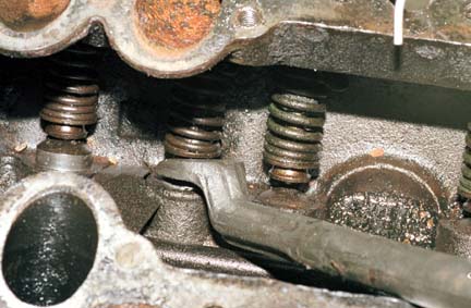
You will probably find that the valve locks are pretty well stuck
to the spring retainers. It will make life easier if they are freed
up before using a modern spring compressor to remove the valve locks.
Just insert the tool under the spring retainers.

Then pry up. Unless the valve is frozen in the guide, the valve
usually lifts instead of the desired action of the locks breaking
loose from the spring retainers. Just tap the valve head with a
hammer while lifting up on the tool and it usually breaks free. Note
that these are the '52-'53 two piece spring retainers. Most hot
rodders prefer to replace these with '49-'51 retainers and matching
after market springs.
 Now I can clamp on the valve spring compressor.
 Use a screwdriver to flick the locks to the side. No sense
in risking fingers on this.
Use a screwdriver to flick the locks to the side. No sense
in risking fingers on this.

Pry up the valve and remove it, then pry the spring and spring
retainers out with a big screwdriver. Finally, drive the guide down
from the top using a deep socket of the right size or a half inch
extension so you don't mangle the hole in the guide or the block.
Sticking out of the top of the spring on the left is a tab with a
hole in it. This is part of one of the "C clip" valve guide
retainers. More about that later.
That's it for now since this is as far as I've gotten to date and
I'm out of pictures. I'll update with the rest of the process in the
future.
Source: http://flatheaddrag.com/gpf.html


it is here to be here from it Antifreeze coolant to be here from it over here for all over here
ReplyDeleteWhat a detailed look at classic engines! Keeping any vehicle running smoothly requires not just care, but also a reliable vehicle repair shop. At Kwik Kar Auto Dallas, we provide top-notch Car Repair Services and Car Repair and Maintenance, ensuring every car gets proper Auto Care and Vehicle Repair. Whether it’s routine Car Maintenance or more extensive repairs, our Auto Repair Shop and Car Repair Workshop handle all Automotive Repair Services with expertise. If you’re searching for a trusted vehicle repair shop, planning ahead can save time and reduce repair costs.
ReplyDelete