Showing posts with label engine. Show all posts

Tuesday, March 10, 2015

Model A Engine Specifications Specs


Ford Model A Engine Specifications

Nut Sizes:
  • Front Motor Mount Castle Nut: 7/16″-20
  • Engine Head Nuts (grade 8): 7/16″-20
  • Connecting Rod Castle Nut: 7/16″-20
  • Ratchet Nut (attaches bottom pulley to crankshaft): 5/8″-18
  • Main Bearing Bolt Castle Nut: 1/2″-20
Stud Sizes:
  • Regular Head Studs: 3 1/2″ Long
  • Water Neck Studs: 5 3/4″ Long
Bolt Sizes:
  • Flywheel to Crankshaft Bolts: Four 7/16-20 by 13/16″ Long
  • Flywheel Housing to Block: Four 7/16″-14 by 1 1/16″ Long and two 7/16-14 by 1 11/16″ Long
  • Timing Cover Bolts: 3/8″-16 by 1 1/8″ Long
  • Side Timing Gear Bolts:One 7/16″-14 by 2 3/16″ Long and one 7/16″-14 by 1 3/8″ Long (lock washers can be used)
Torque Specs:
  • High Compression Head: 65 lbs
  • Standard Head: 55 lbs
  • Main Bearing Cap Torque 80-100 lbs
  • Flywheel Bolt Torque 65 ft/lbs
Specifications:
  • The stock compression ratio was about 4.22:1
  • Piston displacement 200.5 cu. Inches
  • Bore 3.875″
  • Rated H.P. 24.03 SAE
  • Brake H.P. 40
  • Firing Order 1-2-4-3
  • Stroke 4.250″
  • Gas Tank
    • 28/29– 10 GAL.
    • 30/31– 11 GAL.
Valves:
  • Valve lift .287″
  • Seat Angle: 45°
  • Stem Diameter: .311″
  • Port Diameter: 1 3/8″
  • Valve Opening Diameter: 1 3/8″
  • Valve Guide Clearance:
  • Exhaust: .002″
  • Intake: .001-.0015
  • Valve Spring Length:
  • Free: 2 15/16″
  • Compressed Length: 2 1/4″
  • Valve Spring Force (compressed): 57-64 lbs.
  • Valve Timing:
    • Intake:
      • Opens 7 1/2° before TDC (top dead center)
      • Closes 48 1/2° after BDC (bottom dead center)
    • Exhaust:
      • Opens 51 1/2° before BDC
      • Closes 4 1/2° after TDC
Flywheel:
  • Weight: 63 lbs., 4 oz.
  • Balance: Within .15 In/oz.
  • Clutch Mounting Surface: True with crankshaft within .005″ TIR.
  • Clutch Mounting Shoulder Diameter: Concentric with crank flange diameter within .005″ TIR.
Carburetor:
  • Throat Size: 1″
  • Float Level: 1″ from float to machined surface.
  • Main Jet: #63 drill bit
  • Cap Jet: #63 drill bit
  • Idle Jet: # 75 drill bit
Carburetor Assembly
Click Image to Enlarge
Carburetor Info
Click Image to Enlarge
Carburetor Adjustment
Click Image to Enlarge
Exhaust System:
  • Exhaust Pipe: 2″ ID (Inside Diameter)
  • Tail Pipe: 1-5/8″ ID
Miscellaneous:
    • To remove a stuck head from a “firing” engine you can loosen the head nuts about 1/8″ from the head and start the motor the compression will pop the head up and the motor will stall.
    • Crankshaft weight 28 lbs.
    • Engine Oil Capacity:
  • From Empty: 5 Quarts
  • Oil Change: 4 1/2 Quarts
  • Spark Plugs: Champion 3X, 7/8″-18
  • Spark Gap: .035″
Engine Oiling System
Model A Engine Head Torquing Procedure


IMG_1016
IMG_1014


Source:  http://www.motormayhem.net/model-a-ford-reference-page/engine-specifications/

Saturday, May 11, 2013

Prehistoric Bangers By Thom Taylor, Photography by Randy Lorentzen


Bangers are bitchin’, and prehistoric bangers are better yet. There are many dedicated fans of the old-and-slow 201ci, L-head four-bangers originally found in millions of Ford Model Ts, and Model A/B/C-equipped ’28–’34 Fords—and especially of the speed equipment manufactured for them. The good news is they’re popular enough that you don’t need to sweat scouring endless swap-meet spaces to score a find—much of it is reproduced and better than new. Bangers are now hotter than ever. 

There was a time when the whole of hot rodding was based on making old Model Ts and later Model As run as fast or faster than anything in Anytown, USA. For the few who could afford it, a reground cam, improved ignition, and an overhead conversion could make a stripped-down roadster dance to the tune of 115 mph on the dry lakes. Bangers were the hardware to beat, even into the Ford flathead V8 era until about 1938, when hot rodders were able to apply their talents to four more cylinders—and the rest is hot rod history. Their depression-era cost and obsolescence after WWII make them a genuine score today.

For those eager to learn more, there’s the Secrets of Speed Society (SecretsOfSpeed.com), which publishes a quarterly journal with lots of tech and also holds meets throughout the year, where you can see and hear first-hand what the commotion is all about for a modest yearly membership.

If you’re ever near Lincoln, Nebraska, Speedy Bill’s Museum of American Speed (MuseumOfAmericanSpeed.com) is a treasure trove of virtually every speed part ever made, including super-rare and one-off banger hardware, plus long forgotten overhead conversions like Cook, Fargo, and Rutherford. 

Once your roadster is running and you’re ready for something more than “motorvating,” the Southern California Timing Association (SCTA) has classes for racing both vintage flathead fours (VF4) and vintage overhead four-bangers (V4)—with Bonneville records of 152.1 mph in Gas Roadster and 169.3 mph in the Fuel Roadster class! Yes, you really can caffeinate half-an-eight. 

Our friends at H&H Flatheads (Flatheads-Forever.com) in La Crescenta, California, have been collecting and assembling hot bangers for years and were kind enough to let us photograph these coveted gems. Check out what vintage speed looks like.

The A-B-Cs of As, Bs, and Cs

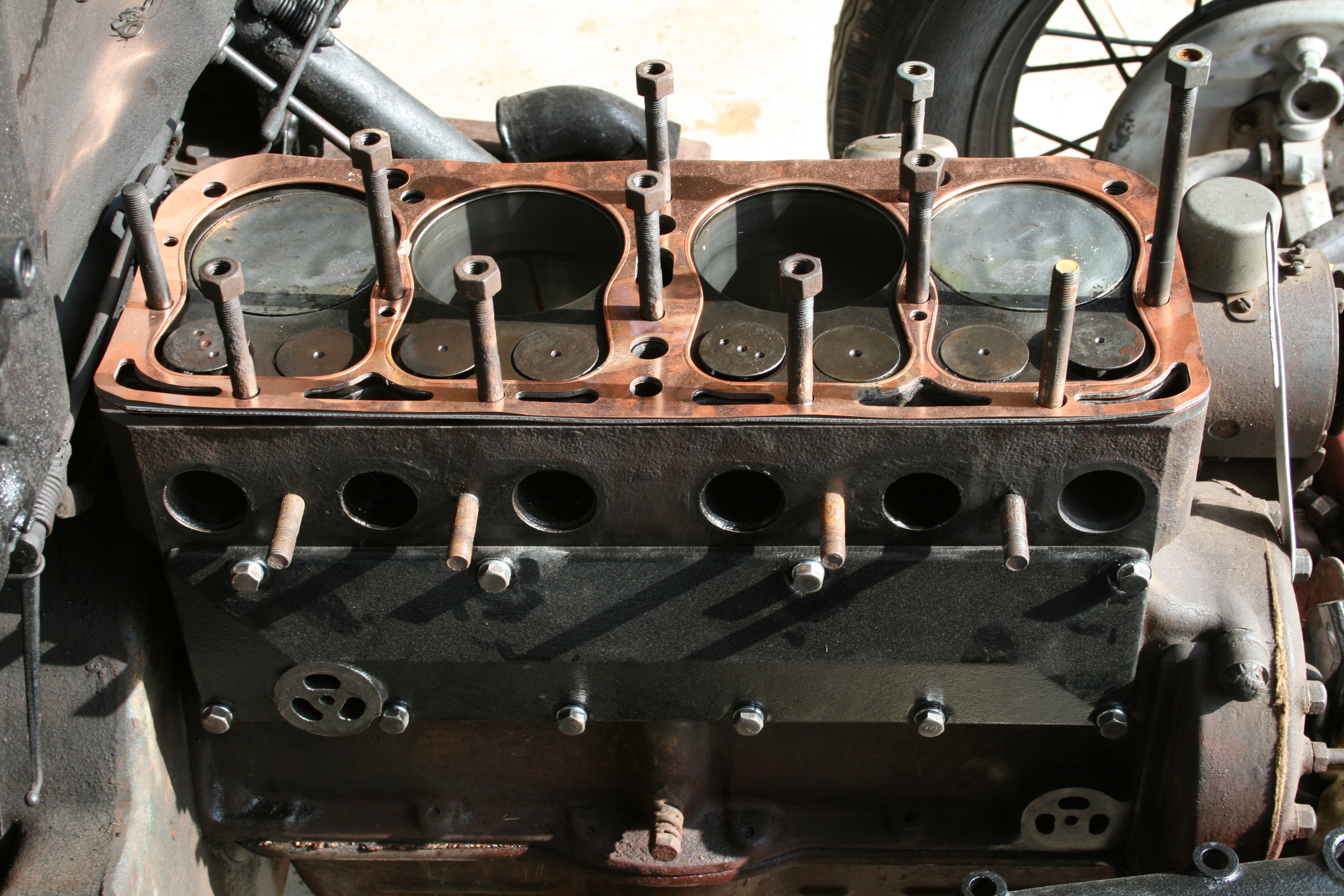
All Ford four-bangers are L-head configuration in stock form—which means the valves are in the block. That’s why the overhead conversions are conversions. Riley heads contain the intake valves while retaining the stock exhaust valve location in the block (surrounded by water jackets). Miller heads contain both intake and exhaust valves for a true overhead valve or F-head configuration.

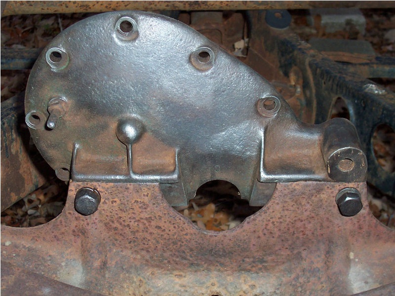
Model A engines are rated at 40 hp stock. They use a smaller crank than their B and C counterparts, and use a gravity-feed or “splash-n-drip” oil system—not a pressurized oil system. 

Model B engines feature a larger crank with no counterweights and a four-bolt water pump. They feature a pressurized oil system with direct lubrication to the mains. The oil galleys can be tapped to provide better lubrication for the crank, cam, and timing gears. 

Model C engines pick up all of the advances of the B, but feature a counterweighted crank, a lighter flywheel—offsetting the crank counterweight’s heft—and a three-hole water pump that will help you eyeball the difference at a swap meet or estate sale. 

Whichever engine is used, H&H modifies the stock oil pump to redirect the oil by running tubes directly to the main and cam bearings and timing gears.

Miller-Schofield Conversions

Hrdp 1210 Vintage Ford Model A B C Four Cylinder Engines 04
The Miller-Schofield overhead conversion was designed by Leo Goosen for race-car builder extraordinaire Harry Miller and was funded by a consortium of businessmen led by George L. Schofield. Their plan was to capitalize on the presumed long run of Model As spewing out of Ford’s plants. Model As were produced from 1928 to 1931. With Miller’s collapsing fortunes, the Miller Hi Speed head tooling was soon sold to Cragar and slightly reworked as a Cragar head sold through Bell Auto Parts. (Yes, Cragar S/S wheels are the offspring of this long-ago race-parts manufacturer.) Among many racing triumphs, the team of Miller and Goosen were best known for developing the Offy engine that dominated Indy for decades. 

Dan Webb’s green B-block seen above started life in his original Model B standard Deuce sedan, stored in a barn for over 55 years! The Burton, Michigan, resident decided to retain it and contacted H&H to do a rebuild with a repro Miller-Schofield overhead conversion. 

Hrdp 1210 Vintage Ford Model A B C Four Cylinder Engines 05
The similar but blingy blue banger below started as a Model A block and is destined for Jim Norman’s ’31 Model A cabriolet from Southern California. Though his A is a restoration, it’s more of a touring car than a show car. 

Both Miller-Schofield conversions run reproduction Stromberg 97 carburetion—a single on the Norman A and a log intake with dual 97s on the Webb B. Additionally, on the Webb engine, a vintage Wico magneto handles spark. 

Internally, H&H assembled both Millers with its private-label cam and forged rods, forged Arias pop-up pistons, steel-sleeved standard-bore holes, line-bored inserts (eliminating the original babbit bearings), Scat crank, and ceramic sealed-water jackets. 

Says Dan, “The sedan loves 60 mph—that’s its sweet spot. There’s still more grunt there, but even at 60, you know this is the fastest this old sedan has ever run.” And the sound? “I ran a 2-inch straight pipe, no muffler, and reduced it to the original, rusted 11⁄2-inch exhaust. It sounds like a screaming banshee and feels like a laser cutter when you walk past it.”

Do “Model C” Engines Really Exist?

Don’t let the old timers tell you otherwise—Ford made lots of Model C engines, though they were not referred to as Model C by Ford. Bangers became an option, not a separate model designation, but the public still called them Model Cs. They were available in both passenger cars and trucks in 1933 and 1934, and they have improvements and differences from their Model B counterparts. Henry Ford used up everything he had in his manufacturing plants, which is why some ’34 Fords ended up with bangers. There were 263,765 Model B and C engines produced between March 9, 1932 and late 1934.
  • Hrdp 1210 Vintage Ford Model A B C Four Cylinder Engines 07
  • Hrdp 1210 Vintage Ford Model A B C Four Cylinder Engines 08
  • Hrdp 1210 Vintage Ford Model A B C Four Cylinder Engines 09

Riley Four-Port Conversions

Hrdp 1210 Vintage Ford Model A B C Four Cylinder Engines 10
The Riley two- and four-port overhead conversions were the brainchild of George Riley, an inventor who also raced cars, planes, and boats. Among other creations, he came up with the inboard/outboard boat engine configuration. 

He opened his shop in 1919 to produce speed equipment for Model Ts and continued to build new Ford speed equipment for years. He also created many wild, one-off race engines, including some cool opposed-two-cylinder midget motors. His four-port head first came on the race scene in August 1932. 

Riley stated that the high point of his career was when the Blue Crown Specials won numerous Indianapolis 500 races in the late ’40s while running his Riley race carburetors. 

The Riley four-port conversions shown on these pages both feature vintage heads—one that’s cast iron from 1938 (red engine), the other a later, rarer aluminum version from 1948 (white engine). Both Rileys are race engines. The white version features original Riley sidedraft carbs sold as a package. In fact, this particular head is as it originally came from George Riley himself. It was built in the ’50s.
Hrdp 1210 Vintage Ford Model A B C Four Cylinder Engines 11

Max Herman Jr. of H&H says the sidedrafts make a direct blast to the cylinders, with no twists or turns like a top- or bottom-draft carburetor—meaning they take in more air quickly. More air in = more power out. 

Besides the Riley carbs, the white engine also features a Model C crank drilled for a pressurized oil system and Buick rods and pistons. Both run bigger, better forged stainless valves, springs, iron guides, and original rockers that are re-bushed and re-shafted. 

The red Riley features the more popular Winfield carburetors run on many a race motor of the era. These, as well as the stalwart Stromberg 97, are what you’ll find on most hopped-up bangers.
Both Riley’s run “split-grind” cams, which means the exhaust lobes are ground differently than the intake lobes—saving wear and tear on the valves as opposed to a race-grind cam used with a high-compression flathead. 

Riley also manufactured a milder two-port head conversion, which can easily be distinguished by the exhaust and intake being located on the same side of the engine.


Source: http://www.hotrod.com/thehistoryof/retrospective/hrdp_1210_vintage_ford_model_a_b_c_four_cylinder_engines/

Friday, May 10, 2013

Diamond Block Model B Ford Engine

What I know about the Diamond block:

The Diamond was the factory identification for post production replacement manufactured engine parts. The blocks had a diamond cast into them just above the cam gear inspection cover. The heads had the diamond cast under the water pump boss. There were A diamond blocks and B diamond blocks. The Diamond block castings are the same as what ever the factory was making when they stoped putting them in production vehicles.

Diamond A engine-

Same as the late '31 block. only difference I've seen is the rear main boss is beefier. Some people have noted hardened valve seat in the exhaust. No verification that this was done by the factory. There are reports of people that have these engines with counter weighted cranks, but if they did come from the factory that way, then they were very late (40's prewar) replacement engines with the pinned on counter weights.


Diamond B engine -

Block is same as last of the production build. Not all had counter weighted cranks. These were avalible as complete engines OR bare blocks. If you needed a new block this is what you got from the dealer as a replacement. Diamond blocks do not always mean that there is a counterweighted crank inside!!!!!!!!! I've been told that the casting is thicker in some areas, but I have not fond anything to document that.

The easiest way to tell if the engine has counter weights is to pull the breather tube and shine a flash light down in through the hole in the block. if you rotate the crank, you can see the #2 crank throw. If you see weights, your Money.


Thursday, March 14, 2013

Donavan Aluminium Model-D Engine


Model-D All Aluminum Ford Model "A" Engine Block


  • Aluminum A356-T6 Block
  • Weighs 70 lbs
  • Ductile Dry Liners
  • 3-7/8" Bore x 4-1/4" Stroke
  • 4340 Steel Billet Crankshaft
  • 4340 Steel Billet Connecting Rods With 45-Degree Off-Set Parting Lines
  • Five Main Bearings
  • Five Cam Bearings
  • Four-Bolt Mains
  • Small-Block Rear Main Seal
  • Small-Block Rod Bearings
  • Angled Main Studs
  • 30 P.S.I. Running Oil Pressure
  • Extra-Large Cooling Capacity
  • Double-Runner Intake Manifold
  • 100 HP/124 ft.-lbs. Torque @ 2850 RPM
  • Idles at 450 RPM
  • Over 180 HP Potential!
5 Bolt Mains
A Finned Head is also available

Options:

  • Internal Oil Pressure Relief Valve
  • Stromberg Carburetor Adaptor Plate
  • Dual Stromberg Intake Manifold
  • Side-Port Seal-Off Plate and Valve Plugs for Easy Overhead Valve Conversions
  • Aluminum 356-T6 Flathead

Snyder's


Saturday, January 26, 2013

Ford Model A - Cover for rear camshaft bushing


The rear camshaft bushing is normally open and the cause for oil leaks. It is normally only covered by a gasket between the Engine block and the flywheel housing. If the flywheel housing lays not properly on the engine block, an oil leak is the result. What I did is to close the bushing with a plug. This modification is not my idea, it is published in the book 'The Model A Engine' written by William H. McRee and Paul H. McRee (Page 58/59). In the book they used an existing freeze plug and I have added a blueprint for those who want to make one.
Nockenwellen Deckel
This is the end of the camshaft with the self made plug.
Nockenwellen Deckel
My plug was newly made on a lathe.
Nockenwellen Deckel
This are the blueprints to make your own plug. To get a better view just click here onto blueprint or into the picture.
Nockenwellen Deckel
The camshaft was too long and I had to grind it a little bit until I hat an end play of about 0,5mm between camshaft and freeze plug.
Nockenwellen Deckel
This is how the rear bearing with camshaft inserted looks like.
Nockenwellen Deckel
The freezing plug is a little bit oversized and can be inserted with a hammer. Then make sure that the camshaft does not get in contact on the inner side of the plug. Now you should never see any oil under your flywheel housing.


Ford Model A - Oil hole for rear camshaft bushing


My engine is an early 29er model and has no oil hole at the rear camshaft bushing. In the 'Model A Ford Service Bulletins' is described how you can add this hole correctly. This is a modification which was done also by Ford in former times.
This is the hole where oil can run from the valve chamber directly into the rear bushing.
To get a hole at the right position I used an old bolt and filed a notch on one side. All details are described in the book mentioned above.
The notch acts as a guidance for my long drill to make the hole with the right angle.


Source:  http://www.maurer-markus.ch/ford_a/mod_nockenwellenlager.en.html

Monday, January 21, 2013

Ignition Coil and Polarity


Ignition Coil & Polarity

(THIS MEMO COMES FROM BOB BIDONDE)
Ignition Coil Hookup Connections
 
    The Ignition Coil does not change the direction of current flow, hence it does not change polarity. However, there are more coils in the Secondary Winding inside of the Coil, thus there is more resistance to incoming current flow at the Secondary Winding Terminal, so the Coil's high voltage output to the spark plugs will be less if the Battery is inadvertently connected to the Secondary Winding Terminal. By the way, the higher resistance wastes primary current in the form of heat, and the Coil will run hotter if the Battery (current-in) is connected to the Secondary Terminal instead of the Primary Terminal. Heat reduces coil life!
 
    So now that we know the Primary Terminal on the Ignition Coil is where we want to connect the battery wire, two questions arise to get the connection right in the Model A: (1) Which is the Primary Terminal on the coil? (2) Which is the correct wire from the Battery that connects to the Primary Terminal?
    (1) Using an ohmmeter with one lead in the high voltage output socket, measure the DC resistance at each wire terminal. Connect the Battery wire to terminal with the least resistance to get the highest secondary voltage output to the spark plugs;
    (2) Assuming that the Model A has a 6-volt system wired in accordance with the factory diagram, the BLACK wire from the driver's side of the Terminal Box is the correct wire. If your Model A has non-factory wiring, then find the wire coming from the CHARGE side of the Ammeter and trace it down to the Terminal Box stud. Connect this stud to the Primary Terminal of the Coil.
 
    Do not rely on the markings that may be cast into the coil top at the terminals, and here's why. Before 1955, coils were marked  (-) or BAT at the Primary Winding Terminal, and (+) at the Secondary Winding Terminal because the ignitions of the time were 6-volt (+) ground. By 1956, ignitions went to 12-volts (-) ground, so the Primary Terminal was marked (+) or BAT. So you can see the coil markings may cause you to make the wrong connections for a pre-1956 Ford.
 
    If you find the above confusing, here is a much simpler solution. Buy from your local Model A parts supplier, a gizmo known as a "Ignition Spark & Coil Tester." It costs in the ballpark of $25, and it has lights to indicate if the wiring is right or wrong. This gizmo will earn its price back in gasoline mileage and performance.
 
    Most all coils, 6 and 12-volt alike, for breaker point ignitions are (the same) designed for 6 to 8-volt operation. Note the resistance wire in the figure. In a 12-volt ignition system, the ignition switch has 2 run positions. The START position allows 12 volts into the Primary Coil to get a hot shot high-voltage engine start. When you release the key to the RUN position, the resistance wire is cut into the primary circuit to drop the coil voltage to 6 to 8 volts. The heat from a constant 12-volt input will shorten the life of a breaker point ignition coil.
 
    When converting from 6 to 12-volt operation, you can run a reproduction "Ford" script 6-volt Coil with an external resistor so the Coil operates at 6 to 8 volts. You can also run a 12-volt Coil with an external resistor. However, some 12-volt coils have an internal resistor, and you need to know this to avoid having 2 resistors on the Primary side of the Coil.
 
    Running an antique ignition coil is fool hardy because eventually coils breakdown and cease to function without warning. Do not run an original antique coil in a 12-volt conversion because these old coils will not take the stress of 8 to 12 volts. And "Oh by the way," make sure that the brass terminal ends are soldered to the conductor of the high-voltage wire between the coil and the distributor. Keep the Primary wire connections bright & tight, and the plastic parts of the coil and distributor clean.
 
Bob Bidonde 
 
Coil
 

What's are the differences in the Ford A, B and C engines?


Question: 'What's are the differences in the Ford A, B and C engines?'

The 1932 V-8 was introduced as the 'Ford Model 18.' The four cylinder model was designated the 'Model B.' Although the V-8 was a national sensation and sold very well, there were many four cylinder Model B's produced. Compression of the Model B engine was 4.8; the A was 4.2. The Model B engine produced 50 hp at 2800 rpm; the A produced 40 hp at 2200 rpm. The Model 'B' mains were 2" diameter; mains in the 'A' were 1-5/8". 'B' rods were 1-7/8"; A rods were 1-1/2". The 'B' camshaft provided an increase in valve timing duration which contributed to the 50 hp at 2800 rpm. A diaphragm type fuel pump was mounted to the lower right side of the engine block. The water pump mounted with three bolts instead of four. The oil pump forced oil directly to the main bearings under mild pressure. Along with other valve chamber modifications, the oil return pipe was eliminated. Model 'C;' The 1933-34 Ford four cylinder engine has been unofficially dubbed the Model 'C.' photo of C head here This designation cannot be found in Ford literature or correspondence. It is strictly a user connotation. Changes from the 'B' to the 'C' engine included: a crank shaft employing integrally forged counterbalances, a shortened three bolt water water pump housing and a 39 pound flywheel compared to a 62-1/2 pound flywheel provided with the Model 'A.' (The counterbalances make up the difference.) There were 263,765 Model 'B' (and 'C') engines produced between March 9, 1932 and late 1934.
Ford produced the Model 'B'  4 cylinder engine  from 1932 - 1934, concurrently with the V-8.

Some noticeable differences between the A and B engines.

The Model "A" engine has a oil return tube on the right side of the engine, that extends 
from the lower left corner of the valve cover to the lower right corner of the block. The
"B" engine has no external oil return tube.
The Model "B" engine has a small port on the right side just below the valve chamber
cover for a cam driven fuel pump. This port will either have a fuel pump attached or
have a triangular shaped plate covering the hole.
Both engines use the same manifold gasket. The "A" and "B" manifolds are
interchangeable for either engine. The differences in exhaust manifolds is the angle of
the exhaust tube at the end of the manifold. The "A" is at about 90 degrees (drops
almost straight down) and the "B" manifold drops off at about a 45 degree angle.

Answer above by John Hargrave, Technical Director, MAFCA

-----------------------------------------------------------------------

Modifications to the B engine included "pressure" feed to the main and cam bearings ; hence there was no need to partially fill the valve chamber with oil so that it could feed by gravity through tubes or holes to these bearings. Rather, oil was pumped directly into a gallery below the chamber and through holes which fed the main and cam bearings. The oil return pipe on the A engine carried away the overage and also cooled the oil as it was returned to the pan.
To understand why this was done, one must consider the engineering of the time. With respect to the main bearings of the crankshaft, Favary (see "Motor Vehicle Engineering - Engines" McGraw-Hill Book Company, Inc.) had this to say in 1926: "When the linear speed of the bearings exceeds 1000 feet per minute, it is most important to maintain a film of oil between the bearing surfaces, hence pressure feed for such bearings in high-speed engines is essential." It should also be noted that a certain volume of oil must also circulate through the bearings to cool them.
Since the main bearing journal size on the B engine was increased to 2" from the 1 5/8" diameter of the Model A, and the engine was rated 50 hp at 2800 rpm instead of the previous 40 at 2250, this linear speed of the crankshaft was thus likely to exceed that which was considered "safe" for adequate lubrication using just gravity feed. At these rated speeds, the A crank linear speed is about 957 ft. per minute; the B is a touch over 1465 ft. per minute.

The above article by Phil Mino

---------------------------------------------------------------------

The B Engine has bigger bearing surfaces on the crank, which means tougher bearings that can take higher speeds and compression. The later couonterweighted ones can be balanced very nicely, although a balanced non-counterweighted one is also smooth. The main bearings are pressurized, meaning they will be cooled and lubed better. Its not a difficult thing to have the crank drilled out to pressurize the rod bearings as well. The weakness in the B block is that they tend to crack between the #4 exhaust valve and the cylinder, sometimes in other cylinders too. These cracks can be repaired sometimes. The block should always be magnafluxed before rebuilding it, to insure it is sound. The exhaust and intake ports are shaped for better breathing and ported to allow more air in and out. You can put a B carb on there with a B manifold and get the original higher 50 horsepower, but with a high compression head, you can really get a boost out of the engine.

Source: http://fordsa.homestead.com/enb.html

Sunday, January 20, 2013

26 Degree Only in Racing Environments


The only change was moving the spark plug wires from over-the-valves to the left side. This resulted in 1.5 HP increase at 2500 rpm.  We recommend, for street use, timing to be set at 28 degree advance. We are recommending 26 degrees only in racing environments where idle is not an issue and rpms over 3000 are used.

 Source: http://www.secretsofspeed.com/LION.htm
Source: http://www.secretsofspeed.com/LION.htm

Friday, August 31, 2012

FORD RACING COYOTE ALUMINUM 5.0 CRATE ENGINE M-6007-M50B MUSTANG COBRA BOSS 302

302 Corba Jet


ugly:::

FORD RACING COYOTE ALUMINUM 5.0 CRATE ENGINE M-6007-M50B MUSTANG COBRA BOSS 302


Ford Racing's aluminum 5.0L Mustang Boss 302 crate engine takes the Ti-VCT 5.0L engine to the next level of performance with high flow CNC cylinder heads and revised intake to deliver 444 horsepower and 380 ft.-lb.+ of torque (with premium fuel). The lightweight aluminum cylinder block features cross-bolted main bearing caps and thick main bearing bulkheads for bottom-end strength. For the track, the oil pan features a large sump 8.5 qt capacity with revised oil pan baffling for improved oil control under hard cornering.
  • 444 hp @ 7400 RPM
  • 380 lb-ft of torque @ 4500 RPM
  • High-performance 5.0-liter, four-valve Ti-VCT engine
  • Displacement 302 cu. in. 
  •  3.63 bore x 3.65-in stroke
  • Aluminum block 
  • Forged steel crankshaft
  • Upgraded sinter-forged connecting rods for improved strength
  • Forged aluminum pistons
  • Aluminum cylinder heads, DOHC, four valves per cylinder, variable intake, variable camshaft timing, 
  • High-strength aluminum-alloy cylinder heads with fully CNC-machined ports and chambers for exceptional high-rpm airflow without sacrificing low-speed torque 
  • Sodium-filled exhaust valves for improved heat dissipation
  • 11.0:1 compression ratio
  • Revised composite intake system with shorter runners, inspired by Ford Racing's Daytona Prototype engine program
  • 80 mm single bore "drive by wire" throttlebody
  • Includes manual transmission engine harness and flywheel
  • Vehicle harness and PCM not included
  • Boss 302 crate engine shown with optional Ford blue coil pack covers FRPP part # : M-6P067-M50B and NVH insulator pads, Ford dealer part # :CR3Z-6N041-A. sold separately.
  • Engine mount bosses and bellhousing mount pattern common to 4.6L modular engines.
  • Photo and specs may vary. 
  • Engine weight: 444 lbs


Saturday, February 18, 2012

high compression head


   Brumfield 7.1 CR cylinder head.  NO reserve.  

     You can tell it's a 7.1 because of the recessed spark plug holes.  

     Nothing wrong with this head, just don't need it anymore.  

     If you want more power to make your model A go up the hills, THIS is the cylinder head for you! 

     Feel free to contact me if you have any questions.  

     Be sure to check out my other items as well! 

Thanks!


Wednesday, December 28, 2011

early '28 timing cover


this is an early 1928 timing cover...if you look closely you will notice that the front engine mounting point is the integrated type...where the engine mounting point was mounted directly to the cross member in the frame...Henry deemed it to rough and order a mount that was sprung.